There are two coordinate systems are commonly used by bearing analysts and rotordynamicists:

1. Lund Convention
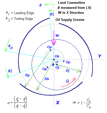
The first Cartesian coordinate system (X,Y,Z) used to describe the bearing orientation and geometry is shown in the following figure. The coordinate system is commonly used by the bearing analysts to study the bearing performance. The X-axis is chosen to be collinear with the bearing load vector (W). Note that X axis does not have to be vertically down as shown in this sketch, it can be in any direction as long as X axis being aligned with the bearing load vector (W), i.e., the load vector can be in any direction. Y-axis is perpendicular with the X-axis in the direction of shaft rotation.  is the circumferential angular coordinate measured from the negative load vector (negative X axis) in the direction of shaft rotation.

A typical 3 lobe bearing using this coordinate system is shown:

The lobe leading and trailing edges for a 20-degree oil supply groove are:

A typical 4-pads tilting pad bearing using this coordinate system is shown:

Note that the tilting pad pivot angle is measured from the Negative Load Vector in Lundís Coordinate System.
2. Standard Convention
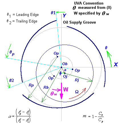
The second Cartesian coordinate system (X,Y,Z) used to describe the bearing geometry, shown in the following figure, is a more conventional standard coordinate system and is commonly used by rotor dynamics analysts for the rotor dynamics study. X-axis is to the right and Y is to the top. The circumferential angular coordinate,  , is measured from the positive X-axis in the direction of shaft rotation. The load vector (W) can be in any direction with respect to the X-axis by a specified angle.

A typical 3 lobe bearing using this coordinate system is shown:

The lobe leading and trailing edges for a 20-degree oil supply groove now are:

A typical 4-pads tilting pad bearing using this coordinate system is shown:

Note that the tilting pad pivot angle is measured from the Positive X-axis in the Standard Coordinate System. The load vector is specified by an angle (θw ) measured from the X-axis.
Each coordinate system has its own strength and weakness. The first coordinate system, commonly referred to be Lundís convention, describes the bearing geometry and load vector orientation by aligning the X-axis with the load vector. It is convenient in the bearing analysis. The disadvantage is that the bearing geometric data are dependent upon the loading direction. For a gear driven rotor, load vector can be in any direction due to the power level (loading condition) of the rotor. Then, for the same bearing analyzed with different loading direction, the bearing geometric data (leading and trailing edges of the lobe) must be re-entered. For the second coordinate system, the bearing geometric data are independent upon the load vector. Additional parameter is required to locate the load vector. The loading direction is specified by an angle. However, it is desirable to know the stiffness and damping coefficients in the loading direction and itís perpendicular axis. Therefore, a coordinate transformation may be needed to transform the bearing coefficients to the loading direction.
Copyright © 2014-2017