Hydrostatic - Hybrid Bearing Analysis
Hydrostatic journal bearing design is very different from the design of hydrodynamic bearings. Many design concepts are fundamentally different; such as increasing the load (or bearing eccentricity) will increase the bearing stiffness due to the higher hydrodynamic resistance for a hydrodynamic bearing. However, increasing the load (or bearing eccentricity) for a hydrostatic bearing may lower the bearing stiffness due to the higher pressure ratio, Pr/Ps (Recess pressure/supply pressure). For hydrostatic bearing, the bearing stiffness is mainly influenced by the Pr/Ps, however, the recess pressure is controlled by the flow through the land and the restrictor (capillary, orifice, etc.). For more information on the hydrostatic bearing design:
H.C. Rippel, “Design of Hydrostatic Bearings,” Machine Design, Part 1-10, Aug. 1 to Dec 5, 1963.
J. P. O’Donoghue and W. B. Rowe, “Hydrostatic Bearing Design,” Tribology, Vol. 2, Feb. 1969.
A. Cameron, “Basic Lubrication Theory,” 1981.
J. Frene, etc., “Hydrodynamic Lubrication: Bearings & Thrust Bearings,” Editor: D. Dowson Elsevier, 1990.
W. B. Rowe, “Hydrostatic, Aerostatic, and Hybrid Bearing Design,”, Elsevier, 2012
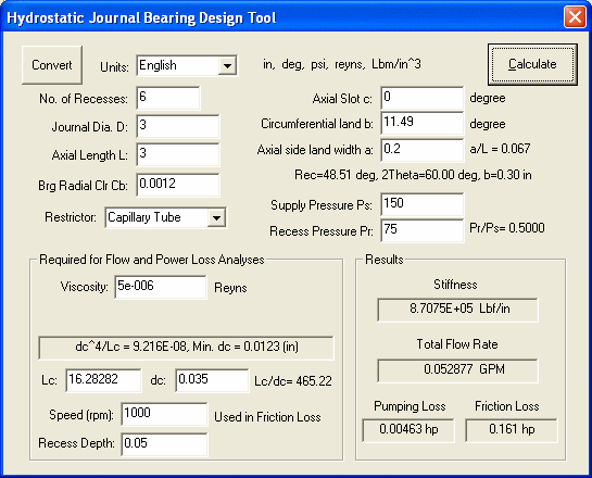
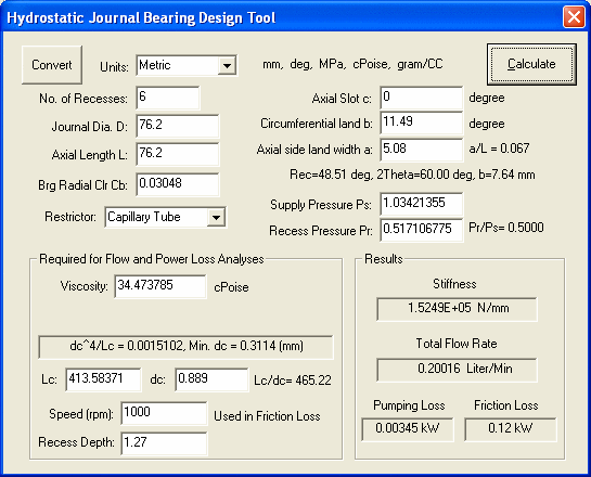
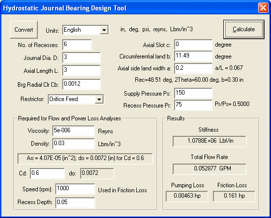
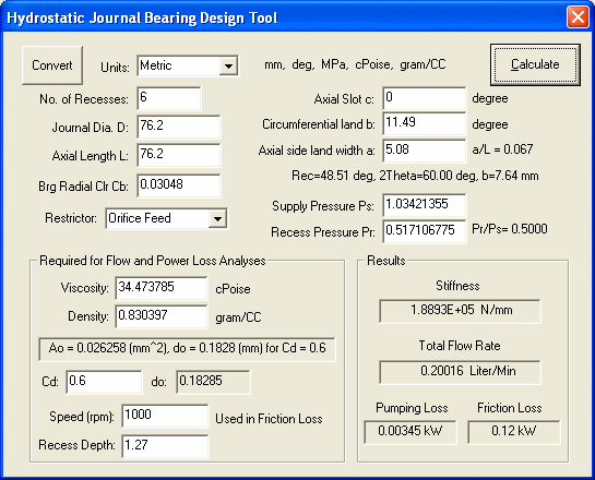
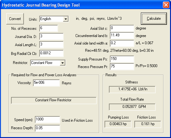
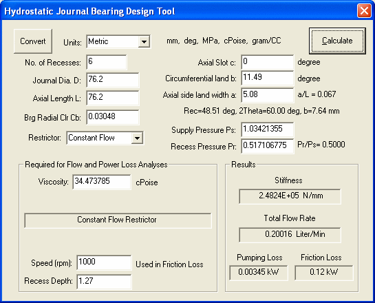
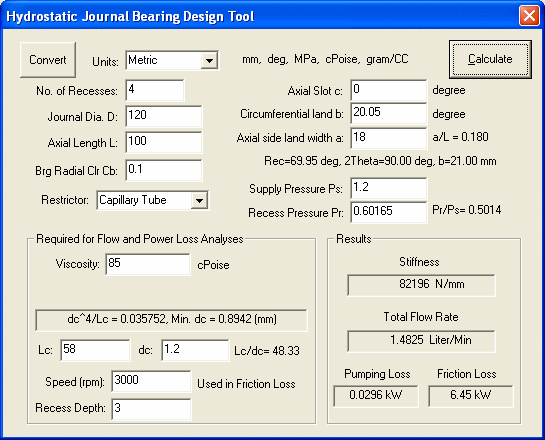
Since the design of the hydrostatic bearing is mainly in the restrictor design, therefore, a design tool is also provided in this program.
Hydrostatic-Hybrid Journal Analysis
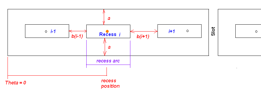
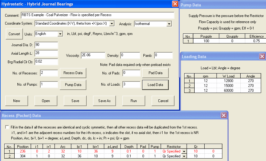
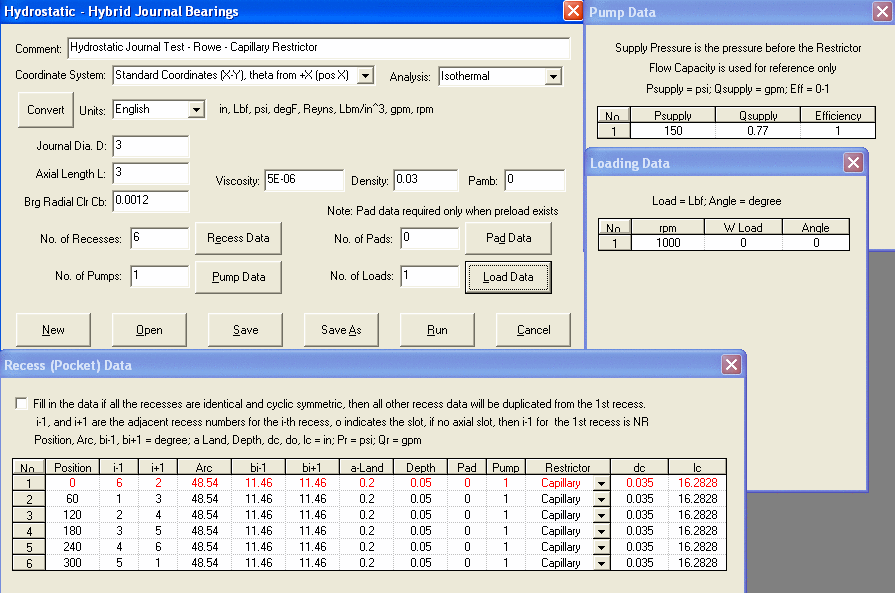
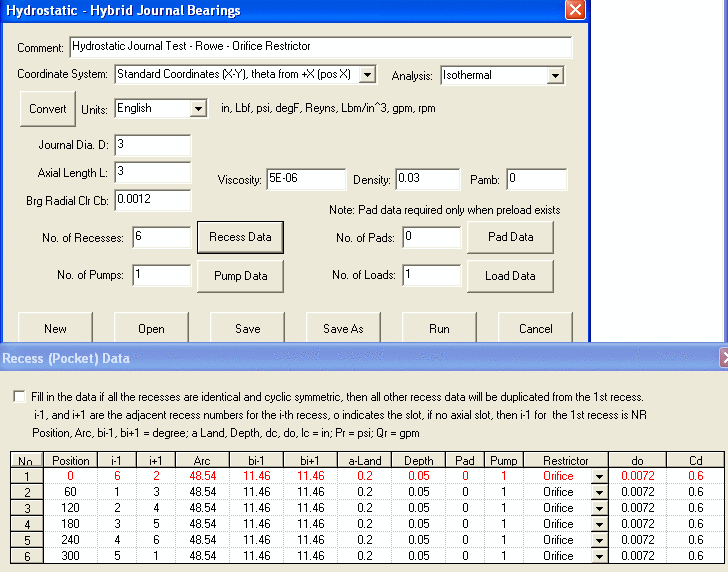
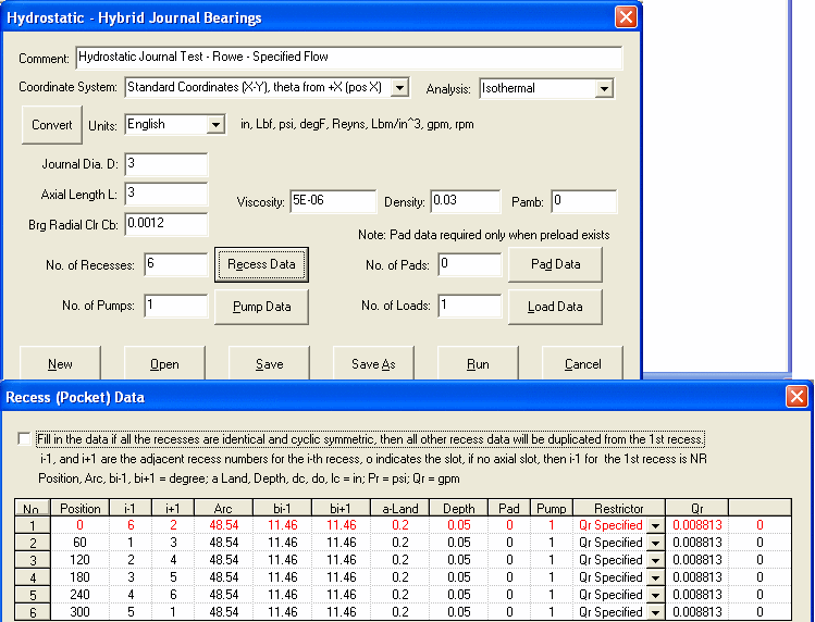
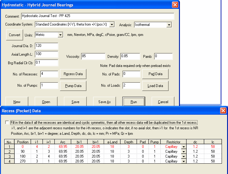
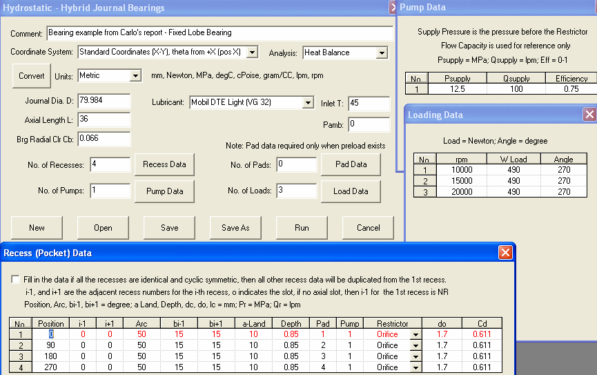
All the inputs are self-explanatory, the recess data are described below:

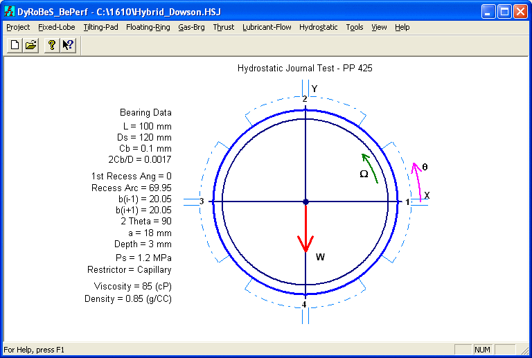
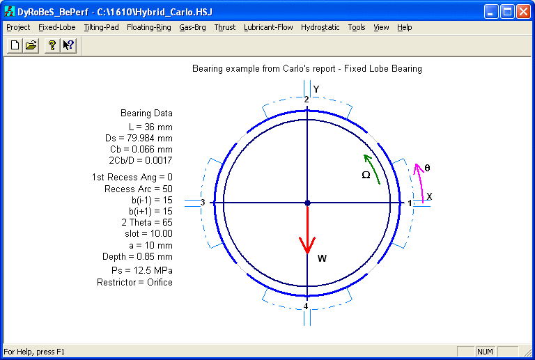
For recess I, the recess position is measured from theta = 0 to the center of the recess. Note that the oil supply hole may not be at the center in many situations. But, that does not affect the recess pressure. Recess position is used to identify the recess location.
I-1 is the previous recess number, it can be 0 if I is connected to the slot, not another recess.
I+1 is the next recess number, it can be 0 if I is connected to the slot, not another recess.
Assuming N is the total recess numbers. For the first recess (I=1), I-1 will be either N (cyclic symmetric and not slot) or 0 (if slot exists). For the last recess (I=N), I+1 will be either 1 (cyclic symmetric and no slot) or 0 if slot exists.
b(I-1) is the inter-recess land between I and I-1.
b(I+1) is the inter-recess land between I and I+1.
a is the axial land width per side.
Pad number is needed only if bearing is preloaded and/or tilting pad bearing. Each pad is separately by the oil slot.
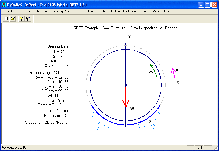
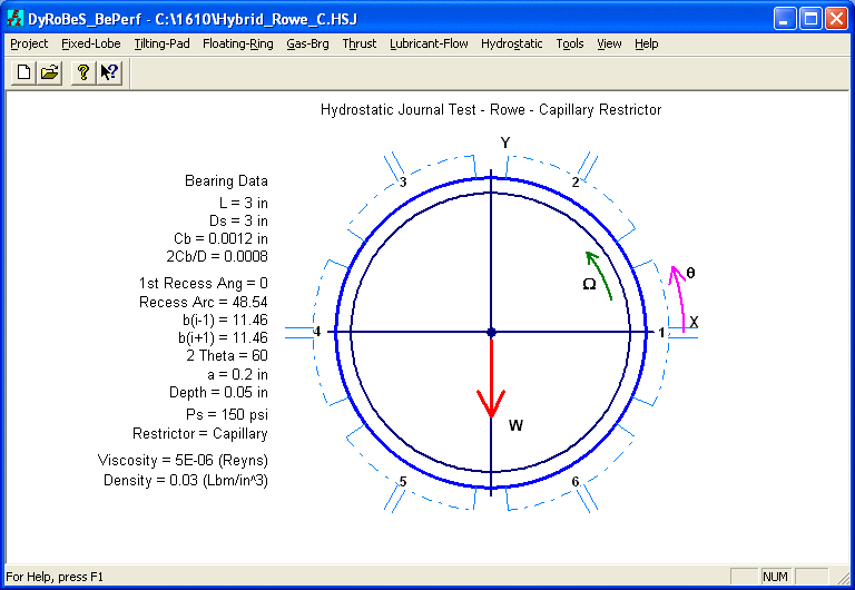
Three different restrictor types can be used in this program: They are: Capillary, Orifice, and constant flow. Many examples are provided for reference.
Hydrostatic Journal Analysis Design Tool
This tool is provided for the restrictor design.
Copyright © 2014-2017