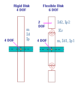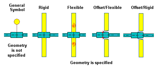
Impellers, fans, turbine blades, collars, coupling hubs, etc, can all be modeled as disks. A concentrated disk can be located at any finite element station. Disks cannot be placed at a substation, and must be placed at stations. Multiple disks are allowed at the same station. For a rigid disk, there are four-degrees-of-freedom (dof), 2 translational and 2 rotational displacements, describing the motion of the disk. These dofs of a disk are the same as the dofs of the finite element station of the rotor (shaft) where the disk is attached to. However, for a flexible disk, two additional rotational dofs are introduced, that is, there is a total of 6 dofs for each flexible disk. The diametral and polar moment of inertias for the inner and outer disks are typically carefully adjusted to match the first disk diametral resonant frequency. Since the outer disk has only 2 rotational dofs and no translational dofs, it only possesses the moments of inertias. All the mass is lumped into the inner disk. The flexible disk option can be important for large overhung rotors, such as large gas turbines where the disk flexibility must be taken into consideration. Depending on the attachment method, the disk can also be offset from the attached station. The symbols used to represent the disk are shown below:


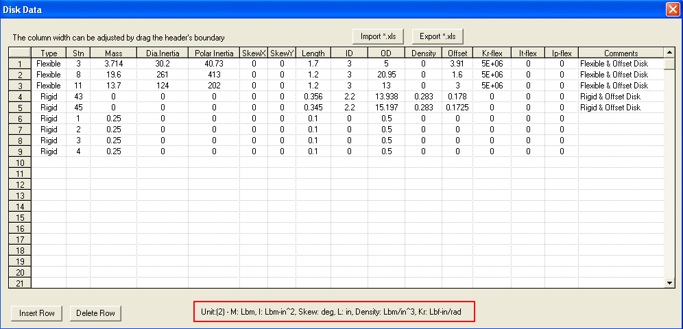
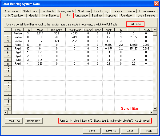
When entering the disks tab (input page), a full table is shown as above figure. You can enter all the data here for a full view. After this full table is closed, a small screen appears, which has the same size as other input pages. You can still edit the disk data using scroll bar in this smaller view. The control buttons <Import *.xls> and <Export *.xls> allow you to import and export the disk data from and to the MS Excel file. You can manipulate the disk data in MS Excel and then Import into DyRoBeS. The <Insert Row> and <Delete Row> allow you to insert a new row or delete a row. <Full Table> allows you to expand the table into a full input page.
The input data for disks are explained below:
1. Type: Rigid or Flexible. Enter R or F.
2. Stn: Station number where the disk is located.
3. Mass: Disk mass.
4. Dia. Inertia: Diametral (transverse) moment of inertia. For a flexible disk, it is the inner disk’s
inertia.
5. Polar Inertia: Polar moment of inertia. For a flexible disk, it is the inner disk’s inertia.
6. Skew x: Disk skew angle about x-axis in degree.
7. Skew y: Disk skew angle about y-axis in degree.
8. Length: Disk axial length.
9. ID: Disk ID.
10. OD: Disk OD. These values are used to graphically display the disk and may be used for the
additional mass properties if the Disk Density is not zero.
If Length and OD are zero, then the disk is represented by a circle and a straight line
connected to the station. If the Length and OD are not zero, the disk is plotted based on
the given Length, ID and OD.
11. Density: Disk density. For a non-zero density entered, additional mass properties calculated
based on the disk geometry (Length, ID, and OD) will be added into the total mass
properties.
Note: for flexible disks, these additional mass properties will be added into the inner disk
properties.
12. Offset: Non-zero value for the offset disk. Positive value if the disk is offset to the right and
negative value if the disk is offset to the left. This value is required only when the disk is
offset from the connecting rotor (shaft) station.
13. Rotational K: Rotational stiffness used to connect the inner and outer disks. Required only
when the disk is flexible.
14. Id (outer): Diametral (transverse) moment of inertia of the outer disk. Used only when the
disk is flexible
15. Ip (outer): Polar moment of inertia of the outer disk. Used only when the disk is flexible
16. Comment: Disk description.
The disk skew angles due to assembly are entered in this folder. However, the total disk skew angles are the combination of the skew caused by assembly and the skew caused by Shaft Bow. For flexible disks, the skew angles are applied on both inner and outer disks. A convenient tool for the calculation of mass properties of a homogeneous solid is provided under Tools menu. You can use this tool to calculate the mass properties of a cylindrical or tapered disk. In the right bottom of the screen, the proper units for the specified unit system are displayed for reference.
For details of using flexible disk and offset disk, see book “Practical Rotordynamics and Fluid Film Bearing Design”, by W. J. Chen.
See also Mass/Inertia Properties Calculation
Copyright © 2014-2017