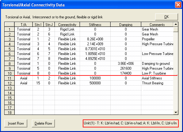
Torsional/Axial Connectivity Data
This option allows you to input the connectivity and constraints for the torsional and/or axial vibration data. For torsional and axial vibrations, the system can be continuous by using the shaft elements and/or discrete by using the external connectivity, or the combination of continuous and discrete model. The discrete data is entered in this option. The connectivity links station I and station J.
1. T/A: Torsional or Axial vibration (enter either T or A).
2. Stn I: Station number I.
3. Stn J: Station number J. If J = 0, station I is connected to the rigid ground.
4. Connectivity: Rigid or Flexible Link. Rigid link indicates that Station I and Station J are rigidly linked and the displacements at Station I and Station J are identical (for example, rigid gear meshes). Flexible link indicates that the Stations I and J are connected by the external stiffness and damping.
5. Stiffness: Used in Flexible Link to connect Station I and Station J.
6. Damping: Used in Flexible Link to connect Station I and Station J.
7. Comment: Description.

See other Torsional/Axial Data Torsional/Axial Data.
Copyright © 2014-2017