Torsional NonLinear Connections and Couplings
This option allows you to include up to five (5) non-linear couplings (or nonlinear connection and elements) in the torsional model. Each non-linear coupling or connection connects two stations, station I and station J. If station J is zero, that means station I is connected to the ground. Rated stiffness will be used in the linear analysis, such as frequency analysis and steady state response. It will be used in the non-linear analysis if the torque-deflection is not given in the table. Linear viscous damping can be specified in the model. Frequency dependent damping is commonly specified using the dynamic magnifier, which exists in the rubber type coupling. The damping value is obtained as:
The damping varies directly with torsional stiffness (K) and inversely with the dynamic magnifier (Dm) and excitation frequency (ω). If the torque-deflection is given, the tangent stiffness will be used, otherwise, the rated stiffness will be used in the damping calculation. This frequency dependent damping can be included in the forced response analysis, such as steady state forced response and transient analysis. Backlash is used if the torsional clearance exists, such as in the gear mesh.
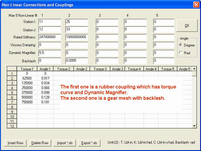
Following input shows two nonlinear connections:
1. A rubber type coupling connects station 11 and 12. Both the rated stiffness and non-linear torque-deflection curve are specified. The rated stiffness will be used in the linear analysis and the torque curve will be used in the nonlinear analysis. The damping exists in the form of dynamic magnifier.
2. Second connection is for gear mesh which connects station 25 and 33. A linear stiffness and backlash are specified. Torque curve is not given, therefore, the rated stiffness will be used in both linear and non-linear analyses.

See other Torsional/Axial Data Torsional/Axial Data.
Copyright © 2014-2017