
Influence coefficient method is used in the balancing calculation. The theory is based on two papers:
Since the least square method is used to solve the simultaneous equations, the Number of Speed Points times the Number of Measured Probes must be greater than or equal to the Number of Balancing Planes. (NsXNm >= Nb).
To use the influence coefficient method, no prior knowledge in rotor mode is required. However, trial weights are required to obtain the influence coefficients.
All the inputs are self-explanatory. They are briefly described below:
1. Number of Balancing Planes: Nb
The balancing planes are the planes along the rotor where the trial weights and balancing corrections are applied. Note that the trial weight can be left-in or removed after the trial run.
2. Number of Measured Probes: Nm
The measurement probes are where the vibrations are taken and recorded. The purpose of the balancing is to find the optimal balancing corrections at the balancing planes such that the vibrations at the measurement probes are minimized.
3. Number of Speeds/Cases: Ns
The number of speeds or cases allows for different speeds or cases, such as idle speed, full speed, full load, unloads, etc…
4. Runout Compensation
Runout can be included or excluded in this balancing calculation.
5. Comments
Up to 3 comment lines can be used to describe the system under study.
6. Shaft Rotation: CCW or CW
7. Phase: Lag or Lead
8. 0 degree: Up or Right.
0 degree position defines the reference mark where all the angles (phases) are measured from.
9. Weighting Factors
Weighting factor allows one to strengthen or weaken the data from the measurement probes or speeds. For example, one may use higher weighting factors for the probes where the critical components are located and/or speeds where the rotor will be operated most of the time. Weighting factor zero indicates that the specific probe data will not be included in the calculation.
Example 1:

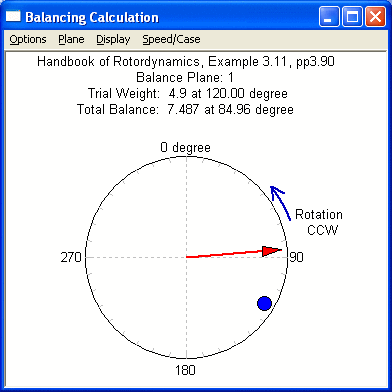
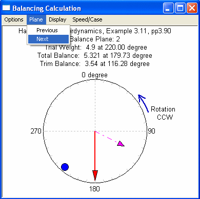
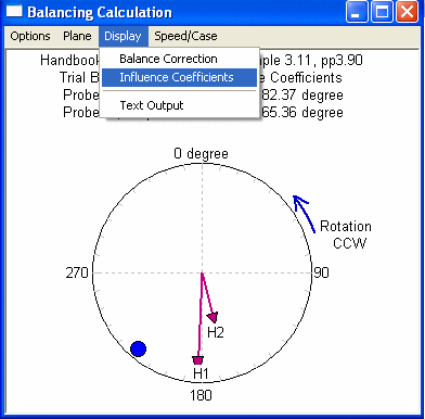
Handbook of Rotordynamics Example 3.11, pp 3.90
Runout Compensation is included
The first trial weight is removed afterward, 2nd trial weight is left-in

   *****  Number of Speeds or Cases   :   1
   *****  Number of Balancing Planes  :   2
   *****  Number of Measurement Probes:   2

   *****  Runout (slow-roll vectors)  *****
      Probe      Amplitude     Phase Angle
        1         0.50000         272.00
        2         0.40000         123.00

   ======  Initial Response (Without Trails)  ======
      Speed   Probe      Amplitude     Phase Angle
        1       1          1.8000         148.00
        1       2          3.6000         115.00

   **************  Trial Unbalance Run: 1  **************
      Plane      Amplitude     Phase Angle   Afterward
        1          4.9000         120.00      Remove

   ---------  Response to Trial Unbalance  ---------
      Speed   Probe      Amplitude     Phase Angle
        1       1          1.1000         178.00
        1       2          2.0000         98.000

   **************  Trial Unbalance Run: 2  **************
      Plane      Amplitude     Phase Angle   Afterward
        2          4.9000         220.00      Left-In

   ---------  Response to Trial Unbalance  ---------
      Speed   Probe      Amplitude     Phase Angle
        1       1          2.1000         98.000
        1       2          3.7000         102.00

   ***  Weighting Factors for probes and speeds ***
        Probe     Weighting Factor
          1            1.0000
          2            1.0000

        Speed     Weighting Factor
          1            1.0000

   ===================================================
   <<<<<<<<  Total Balance Correction  >>>>>>>>
     Correction Required to Balance the Rotor
      Plane No.    Amplitude     Phase Angle
         1          7.4873         84.957
         2          5.3209         179.73


   <<<<<<<<<  Trim Balance Correction  >>>>>>>>>>
     Correction Required if Trial Weight Left-in
     Trim Balance = Total Balance - Trial Weight
      Plane No.    Amplitude     Phase Angle
         2          3.5402         116.28
   ===================================================
   ___________________________________________________

   **********  The Influence Coefficients  ***********
                                 Influence Coef.
     Trial-Run  Speed  Probe   Amplitude    Phase
         1        1      1      0.20617      175.
         1        1      2      0.36446      194.
         2        1      1      0.34092      182.
         2        1      2      0.16986      165.
   ___________________________________________________

   =====================  Predicted Residual Response ========================
                       ----- WithOUT Runout -----    ------ With Runout ------
    Speed   Probe      Amplitude      Phase Angle    Amplitude     Phase Angle
      1       1          0.0000         0.0000        0.50000        272.00
      1       2          0.0000         0.0000        0.40000        123.00
   ===========================================================================
Example 2:
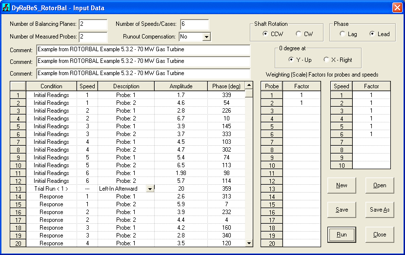
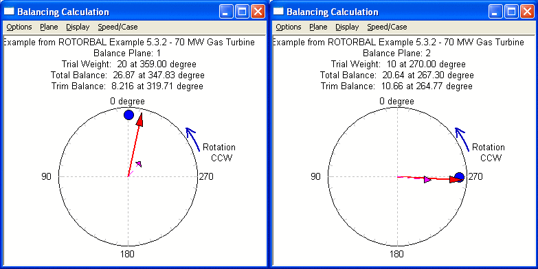
Example from ROTORBAL Example 5.3.2 - 70 MW Gas Turbine
2 probes at 6 speeds
No runout

   *****  Number of Speeds or Cases   :   6
   *****  Number of Balancing Planes  :   2
   *****  Number of Measurement Probes:   2

   *****  NO Runout Compensation

   ======  Initial Response (Without Trails)  ======
      Speed   Probe      Amplitude     Phase Angle
        1       1          1.7000         339.00
        1       2          4.6000         54.000
        2       1          2.8000         226.00
        2       2          6.7000         10.000
        3       1          3.9000         145.00
        3       2          3.7000         333.00
        4       1          4.5000         103.00
        4       2          4.7000         302.00
        5       1          5.4000         74.000
        5       2          6.5000         113.00
        6       1          1.9800         98.000
        6       2          5.7000         114.00

   **************  Trial Unbalance Run: 1  **************
      Plane      Amplitude     Phase Angle   Afterward
        1          20.000         359.00      Left-In

   ---------  Response to Trial Unbalance  ---------
      Speed   Probe      Amplitude     Phase Angle
        1       1          2.6000         313.00
        1       2          5.9000         7.0000
        2       1          3.9000         232.00
        2       2          4.4000         4.0000
        3       1          4.2000         160.00
        3       2          2.8000         340.00
        4       1          3.5000         120.00
        4       2          5.4000         325.00
        5       1          4.1000         73.000
        5       2          3.7000         97.000
        6       1          1.5000         141.00
        6       2          3.1000         99.000

   **************  Trial Unbalance Run: 2  **************
      Plane      Amplitude     Phase Angle   Afterward
        2          10.000         270.00      Left-In

   ---------  Response to Trial Unbalance  ---------
      Speed   Probe      Amplitude     Phase Angle
        1       1          1.8000         319.00
        1       2          4.3000         15.000
        2       1          3.1000         244.00
        2       2          3.4000         9.0000
        3       1          3.2000         107.00
        3       2          1.9000         329.00
        4       1          2.4000         122.00
        4       2          4.4000         330.00
        5       1          2.4000         61.000
        5       2          3.5000         101.00
        6       1          1.0200         170.00
        6       2          3.1100         104.00

   ***  Weighting Factors for probes and speeds ***
        Probe     Weighting Factor
          1            1.0000
          2            1.0000

        Speed     Weighting Factor
          1            1.0000
          2            1.0000
          3            1.0000
          4            1.0000
          5            1.0000
          6            1.0000

   ===================================================
   <<<<<<<<  Total Balance Correction  >>>>>>>>
     Correction Required to Balance the Rotor
      Plane No.    Amplitude     Phase Angle
         1          26.867         347.83
         2          20.639         267.30


   <<<<<<<<<  Trim Balance Correction  >>>>>>>>>>
     Correction Required if Trial Weight Left-in
     Trim Balance = Total Balance - Trial Weight
      Plane No.    Amplitude     Phase Angle
         1          8.2159         319.71
         2          10.660         264.77
   ===================================================
   ___________________________________________________

   **********  The Influence Coefficients  ***********
                                 Influence Coef.
     Trial-Run  Speed  Probe   Amplitude    Phase
         1        1      1      0.65281E-01  279.
         1        1      2      0.21766      317.
         1        2      1      0.57655E-01  248.
         1        2      2      0.11846      202.
         1        3      1      0.54915E-01  228.
         1        3      2      0.49103E-01  134.
         1        4      1      0.77078E-01  242.
         1        4      2      0.10636       26.
         1        5      1      0.65130E-01  258.
         1        5      2      0.15575      313.
         1        6      1      0.67568E-01  230.
         1        6      2      0.14110      312.
         2        1      1      0.83143E-01  210.
         2        1      2      0.17475      257.
         2        2      1      0.10809      105.
         2        2      2      0.10554      258.
         2        3      1      0.34210      118.
         2        3      2      0.10027      271.
         2        4      1      0.11046       26.
         2        4      2      0.10867      214.
         2        5      1      0.18221      359.
         2        5      2      0.32108E-01  318.
         2        6      1      0.78362E-01   12.
         2        6      2      0.27106E-01  279.
   ___________________________________________________

 =======================  Predicted Residual Response ========================
                       ----- WithOUT Runout -----    ------ With Runout ------
    Speed   Probe      Amplitude      Phase Angle    Amplitude     Phase Angle
      1       1          1.0968         310.43         1.0968        310.43
      1       2          2.6067         358.29         2.6067        358.29
      2       1          2.8744         257.03         2.8744        257.03
      2       2          1.7963         40.778         1.7963        40.778
      3       1          4.8509         66.019         4.8509        66.019
      3       2         0.73525         317.09        0.73525        317.09
      4       1          1.6051         154.41         1.6051        154.41
      4       2          4.3282         341.01         4.3282        341.01
      5       1         0.55031         343.11        0.55031        343.11
      5       2          2.1098         114.00         2.1098        114.00
      6       1          1.6347         207.09         1.6347        207.09
      6       2          2.0997         118.93         2.0997        118.93
 =============================================================================
 =============================================================================
Example 3:
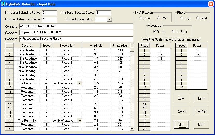
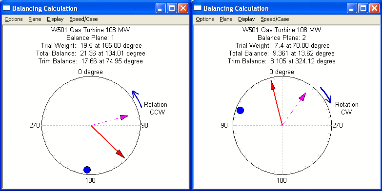
   W501 Gas Turbine 108 MW
   2 Speeds, 3070 RPM, 3600 RPM
   4 Probes and 2 Balancing Planes

   *****  Number of Speeds or Cases   :   2
   *****  Number of Balancing Planes  :   2
   *****  Number of Measurement Probes:   4

   *****  NO Runout Compensation

   ======  Initial Response (Without Trails)  ======
      Speed   Probe      Amplitude     Phase Angle
        1       1          1.1000         143.00
        1       2          3.7000         268.00
        1       3          1.7000         287.00
        1       4         0.80000         156.00
        2       1          3.7000         98.000
        2       2          7.5000         41.000
        2       3          3.9000         1.0000
        2       4          4.2000         209.00

   **************  Trial Unbalance Run: 1  **************
      Plane      Amplitude     Phase Angle   Afterward
        1          19.500         185.00      Left-In

   ---------  Response to Trial Unbalance  ---------
      Speed   Probe      Amplitude     Phase Angle
        1       1          2.5000         70.000
        1       2          1.9000         216.00
        1       3          2.9000         23.000
        1       4          1.9000         216.00
        2       1          2.5000         2.0000
        2       2          6.8000         350.00
        2       3          9.4000         359.00
        2       4          6.3000         202.00

   **************  Trial Unbalance Run: 2  **************
      Plane      Amplitude     Phase Angle   Afterward
        2          7.4000         70.000      Left-In

   ---------  Response to Trial Unbalance  ---------
      Speed   Probe      Amplitude     Phase Angle
        1       1          2.3000         301.00
        1       2          4.4000         216.00
        1       3          2.5000         294.00
        1       4         0.80000         139.00
        2       1          1.7000         12.000
        2       2          5.6000         355.00
        2       3          5.3000         344.00
        2       4          3.8000         181.00

   ***  Weighting Factors for probes and speeds ***
        Probe     Weighting Factor
          1            1.0000
          2            1.2000
          3            1.1000
          4            1.0000

        Speed     Weighting Factor
          1            1.0000
          2            1.2000

   ===================================================
   <<<<<<<<  Total Balance Correction  >>>>>>>>
     Correction Required to Balance the Rotor
      Plane No.    Amplitude     Phase Angle
         1          21.356         134.01
         2          9.3609         13.616


   <<<<<<<<<  Trim Balance Correction  >>>>>>>>>>
     Correction Required if Trial Weight Left-in
     Trim Balance = Total Balance - Trial Weight
      Plane No.    Amplitude     Phase Angle
         1          17.665         74.947
         2          8.1048         324.12
   ===================================================
   ___________________________________________________

   **********  The Influence Coefficients  ***********
     -- Before application of Weighting Factors --
                                 Influence Coef.
     Trial-Run  Speed  Probe   Amplitude    Phase
         1        1      1      0.12406      219.
         1        1      2      0.15077      294.
         1        1      3      0.18008      227.
         1        1      4      0.84732E-01   56.
         1        2      1      0.23984      125.
         1        2      2      0.31737       95.
         1        2      3      0.28226      173.
         1        2      4      0.11241        3.
         2        1      1      0.58558      204.
         2        1      2      0.33784      146.
         2        1      3      0.51293      174.
         2        1      4      0.25519      350.
         2        2      1      0.11851       92.
         2        2      2      0.17773       78.
         2        2      3      0.60743      127.
         2        2      4      0.41498      338.
   ___________________________________________________

=======================  Predicted Residual Response ========================
                      ----- WithOUT Runout -----    ------ With Runout ------
   Speed   Probe      Amplitude      Phase Angle    Amplitude     Phase Angle
     1       1          3.9669         49.648         3.9669        49.648
     1       2          1.9065         348.46         1.9065        348.46
     1       3          2.2628         79.442         2.2628        79.442
     1       4         0.22558         305.47        0.22558        305.47
     2       1          1.8109         9.5156         1.8109        9.5156
     2       2          1.8740         232.93         1.8740        232.93
     2       3          3.3169         159.79         3.3169        159.79
     2       4          1.8632         30.989         1.8632        30.989
=============================================================================
=============================================================================
Copyright © 2014-2017