Introduction
This thrust bearing program has been developed based on the finite element method to accurately predict the performance of various hydrodynamic thrust bearings, such as:
Pad crown can be present and modeled for the tilting pad thrust bearing, particularly when the pivot is centrally located.
The dam (shroud) can be present at inner and outer diameters for the taper land and step thrust bearings.
Currently, only the sector-shape of the pad is allowed for the tilting pad thrust bearing.
The tilting pad geometry is specified by the pad circumferential arc length (degree), and the pad inner and outer diameters.
However, for the taper land and step bearings (fixed profile geometry bearings), commonly the constant oil groove width is specified instead of the pad arc.
For the taper land and step bearings, this program allows for both options:
1. Specify the oil groove with a constant width, or
2. Specify the oil groove with a constant arc at the pitch diameter.
Another unique feature is that this program allows for the partial arc bearing (sometimes called horseshoe type) where the bearing does not have a full 360 degrees extent.
The circular pad is added in Version 2.0.
Three different types of analysis options are included in this program to fully understand the bearing performance:
Another useful design feature provided in this program is the multiple runs, which allows the users to perform multiple design iterations to optimize the design. For multiple runs, only the changed parameters are entered in the table, blank and zero entries indicate the parameters are unchanged from the baseline design.
Bearing Types and Geometry
There are several type bearings available in this program:
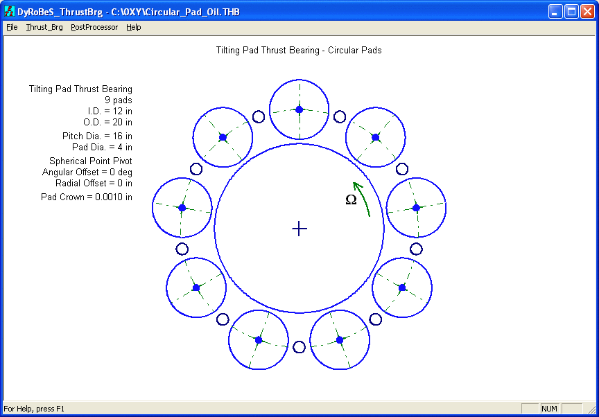
Tilting Pad Thrust Bearing
A typical Tilting Pad Thrust bearing is shown below:
Each pad is described by the pad arc angle γ , and the inner and outer diameters (Di, Do) of the pad (bearing). Two pivot configurations are considered: Point (spherical) pivot and Line (cylindrical) pivot. Pivot location is defined by the circumferential offset and radial offset for the point pivot, and circumferential offset for the line pivot.
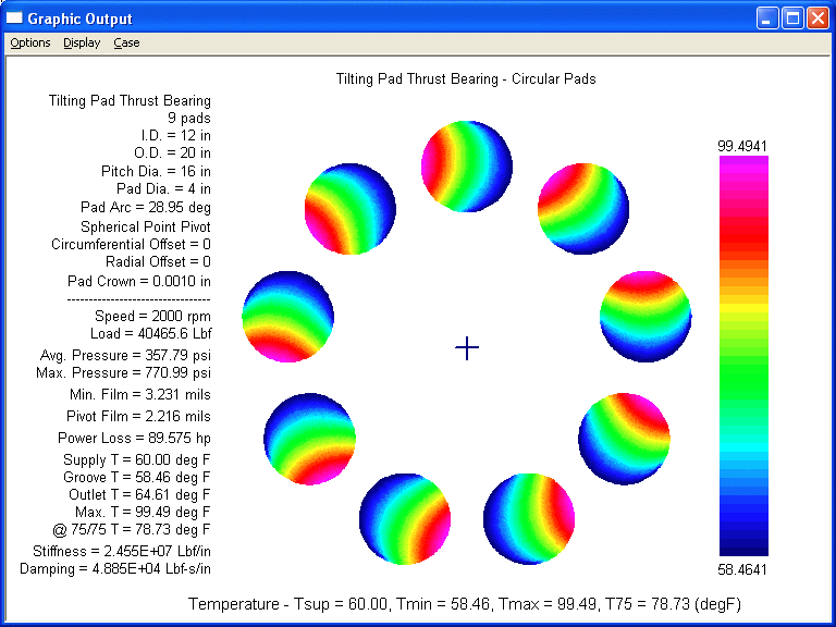
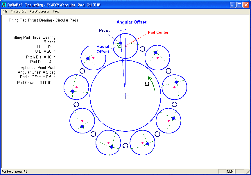
In Version 2, circular pad can be specified. Bearing Type = 6. For a circular pad, the side leakage is hard to define and the oil groove mixing is hard to predict. Therefore, a Leakage Factor (Leakage/Inlet flow) is needed for the temperature prediction. A typical value will be around 0.1-0.3. If the groove oil temperature is known, which can be the supply temperature, then the Hot_Oil_Carry Factor will be ZERO and the leakage flow is not used an any calculation. Another different data entry is to specify the pivot location. For a sector shape, the pivot location is specified by using the circumferential and radial offset factors. These are non-dimensional values and if the pivot is at the center of the sector, then factors of 0.5/0.5 are specified. However, for a circular pad, the offsets are normally specified as the angular and radial distances between the pivot and pad center as shown below.
Taper Land Thrust Bearing
A typical Taper Land Thrust bearing is shown below:
The taper depths are specified at the inner and outer diameters. For a single taper, both taper depths are equal. Linear interpolation is used for the rest of the taper area.
The oil groove is commonly machined with a constant width. A constant groove arc at the pitch diameter can also be specified in this program, as illustrated in the following figure.
If reverse shaft rotation can occur, a bi-directional bearing is needed. A bi-directional taper land thrust bearing is shown below:
Some turbocharger thrust bearings are made with an open end as shown below:
Step Thrust Bearing
If the taper is made with a constant depth in the entire taper area, the taper land bearing becomes a Rayleigh step bearing as shown below:

Data Inputs and Program Menu
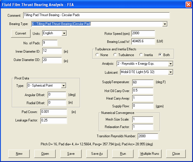
The program is easy to use. Once the program is executed, the main screen is shown below:
There are four options in the main menu, File, Thrust-Brg, Postprocessor, and Help.
The main screen will display the bearing geometry if the bearing data is entered and a file is saved or opened. When the thrustBrg - Input/Analysis is selected, the input screen is displayed as shown below.
The input screen is different for the different bearing type. Currently, there are 5 types of bearing available:
0 – Tilting Pad Thrust Bearing
1 – Taper Land Thrust Bearing
2 – Taper Land Thrust Bearing – Bi-Directional
3 – Rayleigh Step Thrust Bearing
4 – Rayleigh Step Thrust Bearing – Bi-Directional
The inputs for each type bearing are described below.
Tilting Pad Thrust Bearing
All the inputs are self-explanatory. Some are briefly described here. Two pivot configurations are considered: Point pivot and Line pivot. Pivot location is defined by the circumferential offset and radial offset for the point pivot, and circumferential offset for the line pivot.
Three different analysis types are available:
1. Constant viscosity, which only lubricant viscosity and density are required for the inputs. Density is used if turbulence effect is included.
2. Heat balance. In this option, the lubricant properties as a function of temperature are required for the simple heat balance calculation. However, constant viscosity is still used in the Reynolds equation, and the outlet temperature is calculated using the flow and power loss equation.
3. Reynolds equation is solved along with the energy equation for the pressure and temperature distribution of all the finite elements.
Hot Oil Carry Over Factor is used in the oil-groove mixing model to calculate the oil inlet temperature (or groove temperature) to the leading edge of the pad from the supply temperature and the trailing edge oil temperature. In order to reduce the bearing temperature, many bearings are designed such that the more fresh oil from the supply is entered into the leading edge of the pad, and majority of the hot oil from the trailing edge of the pad can be removed through the weep holes or chamfers of the oil groove. When the Hot Oil Carry Over Factor = 0, the inlet temperature at the leading edge of the pad equals to the supply temperature. Typical value ranges between 0.3-1.0.
Heat Carry Away Factor is used to calculate the oil exit (outlet) temperature using the simple heat balance equation. This is the average temperature of the outlet oil from the bearing. Typical value ranges between 0.5-1.0
Supply Oil Flow is used to predict the overall effective oil temperature in the bearing from the simple energy equation, which balances the flow and power. If supply oil flow is larger than the total inlet flow of the bearing, then inlet flow is used. If the supply oil flow is less than the leakage from OD, then the bearing film will be starved and not recommended. The proper supply oil flow will be between the total inlet flow and the side leakage. In the preliminary design stage, this flow is not known yet, then enter zero as a default value.
Transition Reynolds Number is used if the turbulence effect is checked. Turbulence effect will be included only when the local Reynolds number exceeds this transition Reynolds number. There are many publications on this transition Reynolds number ranged between 500 and 2000.
Pad Crown can be specified and applied in both circumferential and radial directions.
There are two numbers which can improve the numerical convergence: 1. Mesh Size Factor which controls the number of finite elements, 2. Relaxation Factor which controls the convergence tolerance.
Mesh Size Scale is used to control the finite element mesh size. The default mesh size is that the pad width in the radial direction (D0-Di)/2 is divided into 30 small segments. And the pad length in the circumferential direction will be divided such that each element will approximately has the same element length in both radial and circumferential directions. To increase the number of elements, use smaller Mesh Size Scale, which will results in smaller element length and larger number of elements. For instance, if Mesh Size Scale = 0.5, there will be approximate 60 node points along the pad width and twice the node points along the circumferential direction, which results in about 4 times more the number of finite elements. 1 is the default value.
Relaxation Factor is used to adjust the convergence tolerance in case that the solution is jumping between two very small numbers. The larger the relaxation factor, the easier convergence will be, which yields the less accurate result. 1 is the default value.
Note that there is a pad summary line shown in the input screen above the option buttons, containing the pad width, length, average pressure, pad arc, etc, when the bearing parameters are changed, this message line is updated accordingly.
Tapered Land Thrust Bearing
Samples of inputs are shown below:
Many of the data inputs are the same as the tilting pad thrust bearing inputs, and others are self-explanatory. There are two check boxes only shown in the fixed pad thrust bearings: Full Bearing and Constant Groove Width. If the Full Bearing box is checked, it indicates that the thrust bearing is a 360 degrees bearing and (Npad * (Pad Arc + Groove Arc) = 360 degrees), therefore, the Pad Arc Angle input is NOT shown in the screen, since groove information is given already. However, if the Full Bearing box is unchecked, which indicates that the bearing can be a partial bearing without a full 360 degrees, then the Pad Arc Angle input appears in the screen and the (Npad * (Pad Arc + Groove Arc) < 360 degrees). Partial bearing has been used in turbochargers.
For fixed pad thrust bearings, the oil groove is commonly machined with a constant width. A constant groove arc at the pitch diameter can also be specified in this program, as illustrated in the following figure.
The groove width and groove arc at the pitch radius are related by:
Groove Width = 2 X rp sin(Groove Arc/2)
A small dam (shroud) at the outer diameter is strongly recommended for the taper land thrust bearing.
Step Thrust Bearing
The inputs for the step thrust bearing are very similar to the Taper Land Thrust Bearing. The step has a constant depth, rather than a taper in the taper land thrust bearing. Due to the manufacturing process, dams are rarely used in the step bearings.
The buttons in the input screen are self-explanatory. The Run button is used to perform a single analysis (case) run, however, the Multiple Runs button allows for the design iteration with multiple runs, as shown below. Enter the values for the changed parameters only, blank and zero inputs indicate the unchanged parameters.
PostProcessor
In the multiple runs, one or more parameters can be changed to study the effect on the bearing performance. Case 0 is the baseline design. It is recommended to run the Single Run first to be sure that the program converges properly before running the multiple runs. The results are summarized in the text and graphic formats. If the analysis type is “0 - Constant Viscosity” or “1 – Heat Balance”, only the Reynolds equation is solved. If the analysis type is Reynolds + Energy equations, the results will include the pressure and temperature distributions. T75 is the temperature at 75/75 position as specified by the API specification for the temperature probe location.
  FileName: C:\DyRoBeS\ThrustFEA\Examples\TiltingPadThrust_01_in.THB

  # of Cases = 3

  Comments: Tilting Pad Thrust Bearing

  Bearing Type: Tilting Pad Thrust Bearing - Point Pivot

  Number of Pads               =     9
  Inner Diameter ID       (in) =    12.0000
  Outer Diameter ID       (in) =    20.0000

  Pad Arc Length         (deg) =      30.00
  Groove Arc Length      (deg) =      10.00
  Pad Crown               (in) =   0.000000

  Circumferential Offset       =     0.6000
  Radial Offset                =     0.5100

  Operating Condition
  Rotor Speed            (rpm) =       2000
  Thrust Load            (Lbf) =   75400.00

  Effect Included:  Turbulence - YES, Inertia - YES
  Transition Reynolds Number: 2000

  Analysis: Reynolds + Energy Eqs.
  Lubricant: Amokon ISO-VG 32
  Supply Temperature   (deg.F) =     120.00
  Supply Oil Flow        (gpm) =     0.0000
  Hot Oil Carry Over Factor    =     0.5000
  Heat Carry Away Factor       =     1.0000

  Mesh Size Scale Factor =   1
  Tolerance Relexation   =   1
 --------------------------------------------------------------------

  Analysis Results:
  Pad Radial Width        (in) =     4.0000
  Pad Circumf. Length     (in) =     4.1888
  Brg Average Pressure   (psi) =     500.01
  Brg Maximum Pressure   (psi) =    1210.75
  Pitch Line Velocity (ft/min) =       8378
  Brg Max. Reynolds Number     =        300

  Pivot Circumf. Tilt    (deg) =   0.028648
  Pivot Radial Tilt      (deg) =  -0.0075003

  Min. Film Thickness   (mils) =      1.052
  Max. Film Thickness   (mils) =      3.695
  Pivot Film Thickness  (mils) =      1.958

  Frictional Power Loss   (hp) =     51.851

  Supply Temperature   (deg.F) =     120.00
  Groove Temperature   (deg.F) =     136.24
  Outlet Temperature   (deg.F) =     160.95
  Maximum Temperature  (deg.F) =     188.09
  Temperature @ 75/75  (deg.F) =     166.12

  Pumping Inlet Flow     (gpm) =    20.1020
  Side Leakage @ ID      (gpm) =     2.3389
  Side Leakage @ OD      (gpm) =     6.3496

  Axial Stiffness     (Lbf/in) =  1.21565E+08
  Axial Damping   (Lbf-sec/in) =  1.80714E+05
 --------------------------------------------------------------------
 --------------------------------------------------------------------

  Case #: 1

  Bearing Type: Tilting Pad Thrust Bearing - Point Pivot

  Number of Pads               =     9
  Inner Diameter ID       (in) =    12.0000
  Outer Diameter ID       (in) =    20.0000

  Pad Arc Length         (deg) =      30.00
  Groove Arc Length      (deg) =      10.00
  Pad Crown               (in) =   0.000000

  Circumferential Offset       =     0.6200
  Radial Offset                =     0.5100

  Operating Condition
  Rotor Speed            (rpm) =       2000
  Thrust Load            (Lbf) =   75400.00

  Effect Included:  Turbulence - YES, Inertia - YES
  Transition Reynolds Number: 2000

  Analysis: Reynolds + Energy Eqs.
  Lubricant: Amokon ISO-VG 32
  Supply Temperature   (deg.F) =     120.00
  Supply Oil Flow        (gpm) =     0.0000
  Hot Oil Carry Over Factor    =     0.5000
  Heat Carry Away Factor       =     1.0000

  Mesh Size Scale Factor =   1
  Tolerance Relexation   =   1
 --------------------------------------------------------------------

  Analysis Results:
  Pad Radial Width        (in) =     4.0000
  Pad Circumf. Length     (in) =     4.1888
  Brg Average Pressure   (psi) =     500.01
  Brg Maximum Pressure   (psi) =    1239.59
  Pitch Line Velocity (ft/min) =       8378
  Brg Max. Reynolds Number     =        320

  Pivot Circumf. Tilt    (deg) =   0.033042
  Pivot Radial Tilt      (deg) =  -0.0080653

  Min. Film Thickness   (mils) =      1.067
  Max. Film Thickness   (mils) =      4.094
  Pivot Film Thickness  (mils) =      2.052

  Frictional Power Loss   (hp) =     51.997

  Supply Temperature   (deg.F) =     120.00
  Groove Temperature   (deg.F) =     134.27
  Outlet Temperature   (deg.F) =     158.52
  Maximum Temperature  (deg.F) =     183.92
  Temperature @ 75/75  (deg.F) =     162.05

  Pumping Inlet Flow     (gpm) =    21.8500
  Side Leakage @ ID      (gpm) =     2.6806
  Side Leakage @ OD      (gpm) =     7.3525

  Axial Stiffness     (Lbf/in) =  1.15246E+08
  Axial Damping   (Lbf-sec/in) =  1.56702E+05
 --------------------------------------------------------------------
 --------------------------------------------------------------------

  Case #: 2

  Bearing Type: Tilting Pad Thrust Bearing - Point Pivot

  Number of Pads               =     9
  Inner Diameter ID       (in) =    12.0000
  Outer Diameter ID       (in) =    20.0000

  Pad Arc Length         (deg) =      30.00
  Groove Arc Length      (deg) =      10.00
  Pad Crown               (in) =   0.000000

  Circumferential Offset       =     0.6500
  Radial Offset                =     0.5100

  Operating Condition
  Rotor Speed            (rpm) =       2000
  Thrust Load            (Lbf) =   75400.00

  Effect Included:  Turbulence - YES, Inertia - YES
  Transition Reynolds Number: 2000

  Analysis: Reynolds + Energy Eqs.
  Lubricant: Amokon ISO-VG 32
  Supply Temperature   (deg.F) =     120.00
  Supply Oil Flow        (gpm) =     0.0000
  Hot Oil Carry Over Factor    =     0.5000
  Heat Carry Away Factor       =     1.0000

  Mesh Size Scale Factor =   1
  Tolerance Relexation   =   1
 --------------------------------------------------------------------

  Analysis Results:
  Pad Radial Width        (in) =     4.0000
  Pad Circumf. Length     (in) =     4.1888
  Brg Average Pressure   (psi) =     500.01
  Brg Maximum Pressure   (psi) =    1352.71
  Pitch Line Velocity (ft/min) =       8378
  Brg Max. Reynolds Number     =        391

  Pivot Circumf. Tilt    (deg) =   0.048679
  Pivot Radial Tilt      (deg) =  -0.010391

  Min. Film Thickness   (mils) =      1.054
  Max. Film Thickness   (mils) =      5.456
  Pivot Film Thickness  (mils) =      2.368

  Frictional Power Loss   (hp) =     52.429

  Supply Temperature   (deg.F) =     120.00
  Groove Temperature   (deg.F) =     129.70
  Outlet Temperature   (deg.F) =     152.82
  Maximum Temperature  (deg.F) =     175.05
  Temperature @ 75/75  (deg.F) =     152.18

  Pumping Inlet Flow     (gpm) =    27.4712
  Side Leakage @ ID      (gpm) =     3.8892
  Side Leakage @ OD      (gpm) =    11.0387

  Axial Stiffness     (Lbf/in) =  1.02335E+08
  Axial Damping   (Lbf-sec/in) =  1.06404E+05
 --------------------------------------------------------------------
 --------------------------------------------------------------------
Copyright © 2014-2017