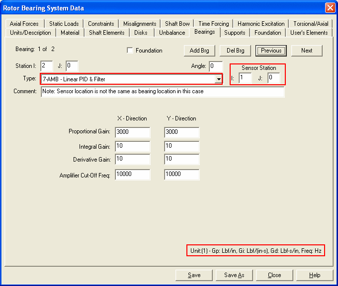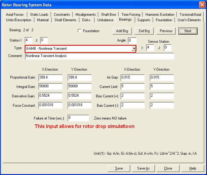
Two options are used to model the active magnetic bearing. The linear Proportional-Integral-Derivative controller with low pass filter is used in the steady state analysis (Stability and Forced Response Analyses). The nonlinear active magnetic bearing requires more input data and is used in the non-linear transient analysis. For both options, the sensor stations may be different from the bearing stations (sensor non-collocation) and the model may be different for the two bearing axes.
Active Magnetic Bearing 1 - Linear PID controller with low pass filter
This bearing is modeled as a PID controller in series with a unity gain, first order low pass filter (generally used to model the amplifier). Two additional degrees of freedom will be added to each of the x and y equations to model the controller states for each bearing. However, these two additional degrees of freedom will not be available for displaying in the post-processor. The output of the PID controller at each axis is:

Where xs is the displacement at sensor location. The control force at each direction in the S-domain is:

Active Magnetic Bearing 2 - Non-Linear Transient Analysis
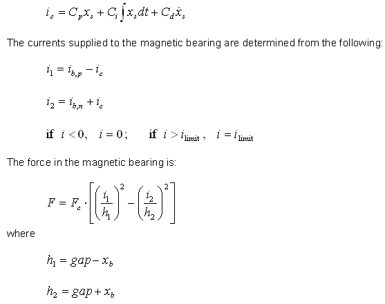
This bearing is a standard PID controlled active magnetic bearing with sensor non-collocation, gap non-linearity and current saturation effects for the transient analysis only. The control current is determined from the following expression:


See also Bearings
Copyright © 2014-2017