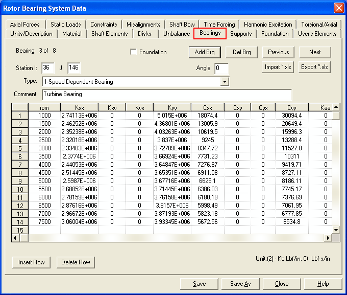
All the bearing/damper/seals/support forces acting on, or interacting between, the rotating assemblies and non-rotating structures fall into this category. Bearing is an interconnection component, which connects two finite element stations (station I and station J). The bearing can be of any type, such as linear/nonlinear, real/pseudo, fluid film, rolling elements, or active magnetic bearings, and aerodynamic forces, seals, fluid coupling, rubbing, etc. Nonlinear bearings can only be used in the time transient analysis, with the exception of squeeze film dampers and generalized non-linear isotropic bearing. Squeeze film dampers (Type-4) and non-linear isotropic bearings (Type-6) can be analyzed in both the steady state synchronous response analysis and time transient analysis. Different types of bearings or even same type bearing can be at the same finite element station depending upon the modeling technique. Numerous predefined bearing types are provided in the program. If you like to define your own bearing type, please contact the program developer for implementation.

Similar to the Shaft Elements input, the control buttons <Add Brg>, <Del Brg>, <Previous>, and <Next> allow you to add a new bearing data, delete an existing bearing, and switch the bearing data for systems with multiple bearings. The <Import *.xls> and <Export *.xls> buttons, shown only when bearing type 1 is selected, allow you to import and export the speed dependent bearing data from and to the MS Excel file.
Some common input data are explained below.
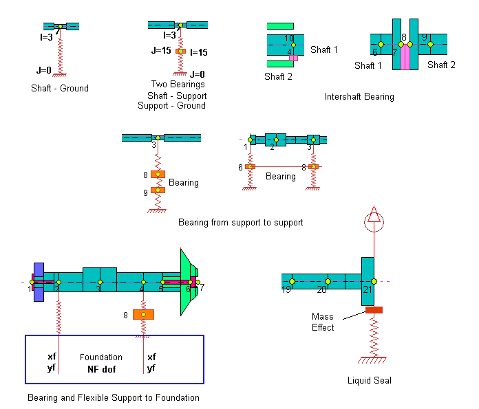
Station I and Station J: A bearing connects two stations. Station I cannot be zero. Station J = 0 if it is connected to the rigid ground. J can also be a connecting station number of an intershaft bearing in a multi-shaft system or the flexible bearing support station number for a flexible support system. Several configurations for the bearing connection are shown below.
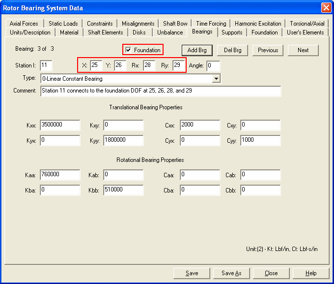
Foundation: If the foundation box is checked, this bearing is connected to the foundation. The foundation data is provided under Foundation tab. If Foundation box is checked, additional inputs (X, Y, Rx, Ry) appear in the screen. The X, Y, Rx, and Ry are the degrees-of-freedom in the foundation. The bearing connects the degrees-of-freedom of the station I to the (X, Y, Rx, Ry) coordinates in the foundation, as shown below:
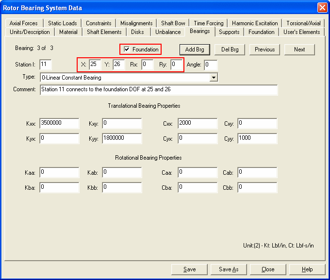
Similar to the Station I and J inputs, if the inputs for (X, Y, Rx, Ry) are zero, then this DOF is constrained and connected to the ground.
See Foundation for more detail.
Angle: Degree measured from the global fixed coordinate system to the local coordinate system where the bearing coefficients are defined. The angle is measured in the counterclockwise direction. The dynamic characteristics of the bearings are usually defined (specified) in the local coordinate system, therefore, a coordinate transformation is performed by the program to convert the bearing stiffnesses and dampings in the local coordinate system to the stiffnesses and dampings in the global coordinate system. In DyRoBeS, it is recommended that this transformation be performed in BePerf for computational efficiency, not in Rotor here.
Comment: Description of this bearing.
Types: Currently, the following types of bearings are supported in the program and they are explained in the following sessions.
2-Bearing coefficients from external data file
6-Generalized non-linear isotropic bearing
7-Active magnetic bearing (Linear Model)
8-Active magnetic bearing (Nonlinear Model)
10-General non-linear polynomial bearing
12-Multi-Lobe hydrodynamic bearing (input data in Rotor)
13-Multi-Lobe hydrodynamic bearing (input data in BePerf)
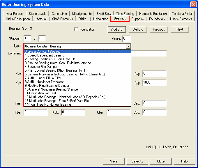
For every different type bearing, the input screen is different. Only the related inputs for the selected type bearing are shown in the screen. Bearing inputs are explained below:
Copyright © 2014-2017