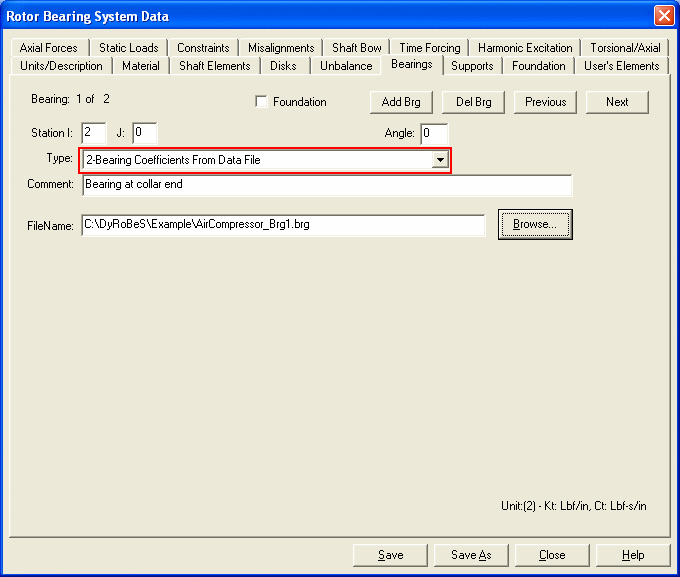
Bearing Coefficients from External Data File
This option allows the analysis program to import bearing coefficients from an external data file. The data filename must include the full path. It is recommended to use Browse button to select the file. The external bearing data file must be in the following ASCII format:
First Line
N, unit, Nc, kRot, 0, 0, 0 comments
N: number of speed points
Unit: unit number, from 0 to 4. See Unit System
Nc: number of brg coefficients, Nc, either 0, 8, 12, or 24
Note: Nc = 8, only translational K and C are considered.
Nc = 12, Translational K, C, and M are considered.
Nc = 24, than all the translational and rotational K, C, and M are considered.
Nc = 0, it will be re-assigned to be 8
KRot = 0 (default) indicates that the bearing coefficients are obtained by assuming the shaft rotation is CCW. Almost all the bearing coefficients are calculated in this way.
KRot = 1 indicates that the bearing coefficients are calculated by assuming the shaft rotation is CW. This option is used for the geared system where different direction of shaft rotation occurs. However, there is a Check option in the Lateral-Torsional-Axial vibration to convert these coefficients. Therefore, kRot == 0 should be used in almost all the cases. It is used mainly for program verification purposes.
repeat N times with the following data
rpm, Kxx,Kxy,Kyx,Kyy,Cxx,Cxy,Cyx,Cyy,Mxx,Mxy,Myx,Myy, Kaa,Kab,Kba,Kbb,Caa,Cab,Cba,Cbb,Maa,Mab,Mba,Mbb,
The rotational speed of shaft 1 is used for the case of multi-shaft systems. Again, If the number of data (speed) points is greater than or equal to 3, a spline function is used in the program to interpolate the coefficients for the shaft speeds requested in the analysis that are not given in the data points. If the number of data (speed) points is equal to 2, a linear function is used to obtain the coefficients for the shaft speeds that are not given in the data points. If there is only one point in the data, then it will be treated as a linear constant bearing. The use of spline function allows a small number of needed data points. Since the spline function is used in the interpolation, the data must be entered in the increasing order according to the speed value. Also, the extrapolation of the data outside the data range can be very unpredictable. Caution must be taken when extrapolating the data.
Example:
 9  2  8  0 0 0 0
 5000  .1832E+06  .1552E+06  -.1603E+06  .1885E+06  672   3    3   689
10000  .3628E+06  .3035E+06  -.3301E+06  .3920E+06  665   3    3   703
15000  .5316E+06  .4536E+06  -.4974E+06  .5726E+06  660   6    6   706
20000  .6935E+06  .6038E+06  -.6649E+06  .7387E+06  657   8    8   707
25000  .8557E+06  .7483E+06  -.8416E+06  .9170E+06  654   8    8   712
30000  .1021E+07  .8852E+06  -.1030E+07  .1117E+07  652   4    4   721
35000  .1190E+07  .1013E+07  -.1233E+07  .1342E+07  650  -5   -5   732
40000  .1364E+07  .1132E+07  -.1450E+07  .1596E+07  647  -10  -10  745
45000  .1544E+07  .1242E+07  -.1682E+07  .1879E+07  645  -15  -15  759
In the above example, only the translational stiffness and damping are considered, therefore, only 8 coefficients are given in the data file.

See also Bearings and Linear bearing
Copyright © 2014-2017