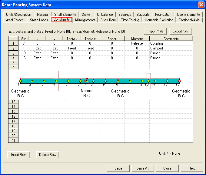
This option allows you to model the geometric and natural boundary conditions. Note that this option is used for the lateral vibration only. For the axial and torsional vibrations, the constraints are entered under the Connectivity of Torsional/Axial Data folder. In the practice of rotordynamics, the geometric constraints are seldom used. They are provided in the program for the theoretical verification with many closed form solutions. The natural boundary conditions (Shear/Moment Release) are used mainly for the simulation of a spline or a flexible coupling with moment release.
1. Stn: Station number where the constraint is imposed.
2. x: Translational displacement in the X axis (Fixed or None).
3. y: Translational displacement in the Y axis (Fixed or None).
3. Theta x: Rotational displacement about X axis (Fixed or None).
4. Theta y: Rotational displacement about Y axis (Fixed or None).
5. Shear: Shear force release (Release or None).
6. Moment: Moment release (Release or None).
7. Comment: Description.
Where x, y, Theta x, and Theta y are geometric boundary condition. Shear and Moment are natural boundary condition. If both geometric and natural constraints are applied at the same finite element station, the natural boundary conditions are ignored.
The <Import *.xls> and <Export *.xls> buttons allow you to import and export data from and to the MS Excel file.

Copyright © 2014-2017