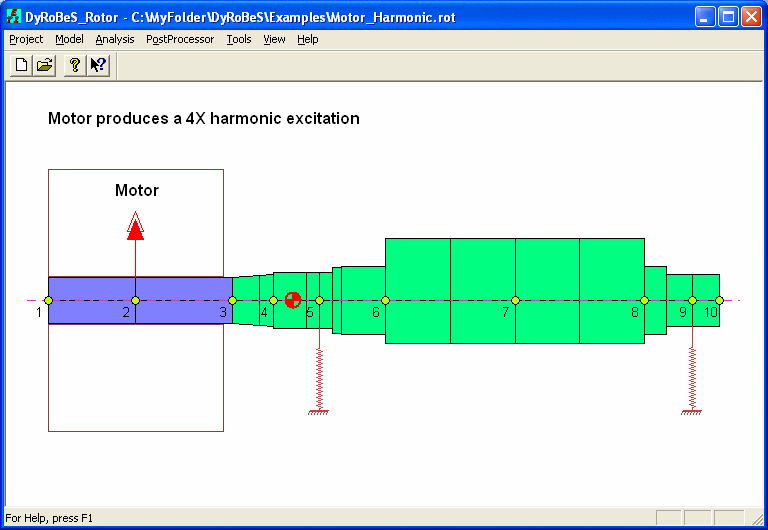
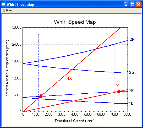
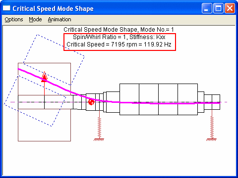
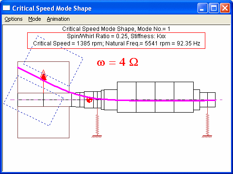
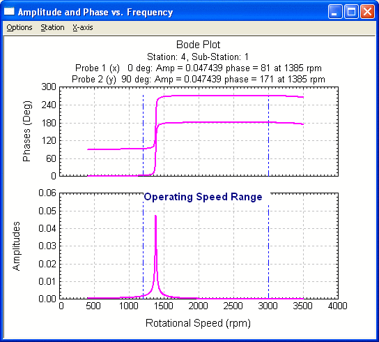
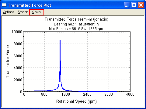
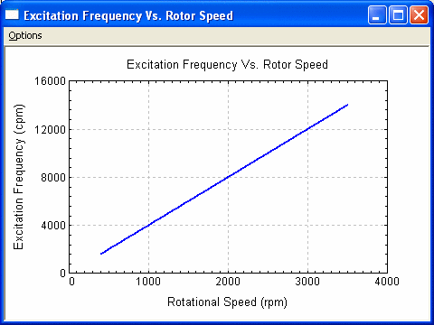
This option is for the steady state harmonic response. A compressor is directly coupled with a motor as shown below. The operating speed range is between 1200 rpm to 3000 rpm, depending on the system requirement. The rotor was designed such that the first synchronous critical speed is about 7200 rpm, which is much higher than the operating speed range. No conventional critical speed (due to mass unbalance) was anticipated during the development stage, ball bearings were used. However, the motor was directly mounted into the rotor and due to the wiring design and mounting eccentricity between rotor and stator, the motor produces a 4X excitation. That means the excitation frequency is 4X of the rotor speed. From the whirl speed map, it shows that the first forward synchronous critical speed is around 7200 rpm, however, the first forward 4X critical speed is around 1385 rpm. That means when the rotor is around 1385 rpm, the 4X excitation from the motor excites the first forward natural frequency. These can also be found using the critical speed analysis with spin/whirl ratio of 1 and ¼. The response shows the peak response occurs around 1385 rpm, which falls into the operating speed range. The problem was resolved by re-design the motor with different wiring method. The X-axis can be plotted either in rotor speed or excitation frequency.
Rotor system

Whirl Speed Map
First undamped forward synchronous critical speed, spin/whirl ratio = 1
First undamped forward 4Xsynchronous critical speed, spin/whirl ratio = 1/4
Response amplitude
Bearing force
Excitation frequency vs. rotor speed
See also Lateral Vibration Analysis, Steady State Harmonic Excitation Response Analysis.
Copyright © 2014-2017