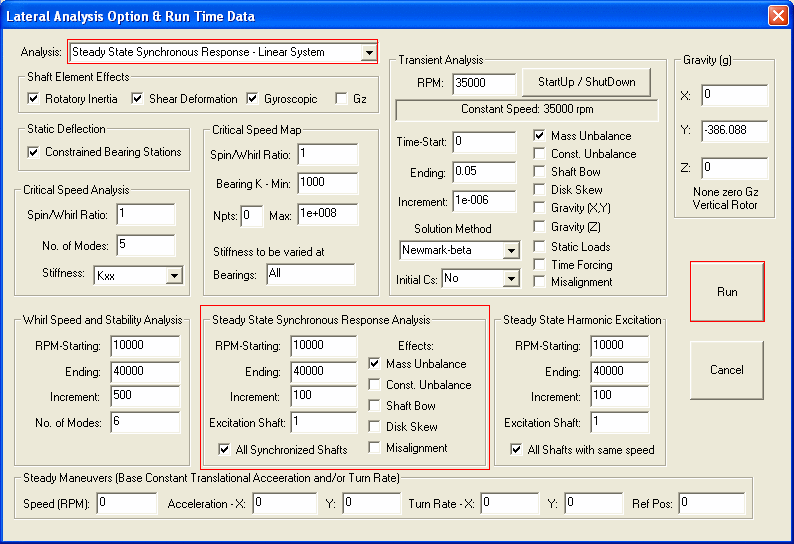
To perform the lateral vibration analysis, the rot-bearing data file (.rot) must be built and opened. From the Main Menu, select Analysis and Lateral Vibration as shown below.

The run time data screen for the Lateral Vibration Analysis is shown below:

The inputs are described:
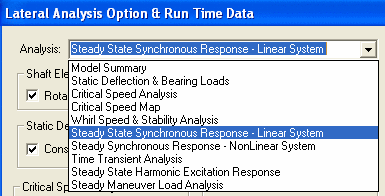
1. Analysis:
Select one analysis at a time as shown below. Once the specific analysis option is selected, the corresponding data are also required.

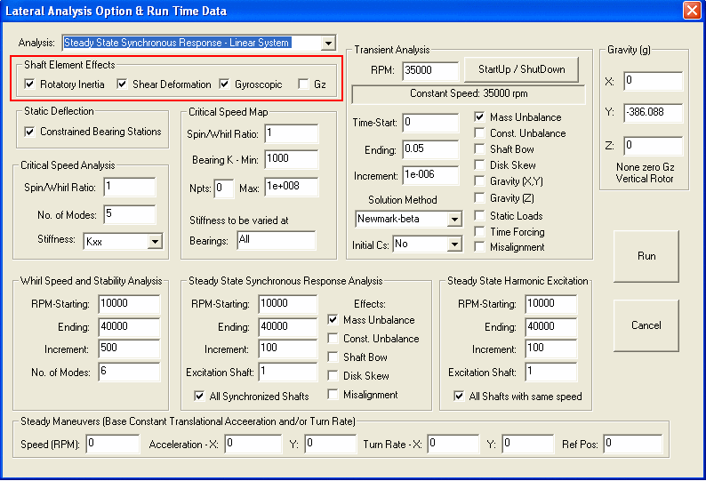
2. Shaft Element Effects
The shaft rotatory inertia, shear deformation, gyroscopic effect, and gravity Z for vertical rotors, can be included or neglected in the calculation by checking the boxes in the run time data. All the effects are included by the default selection.

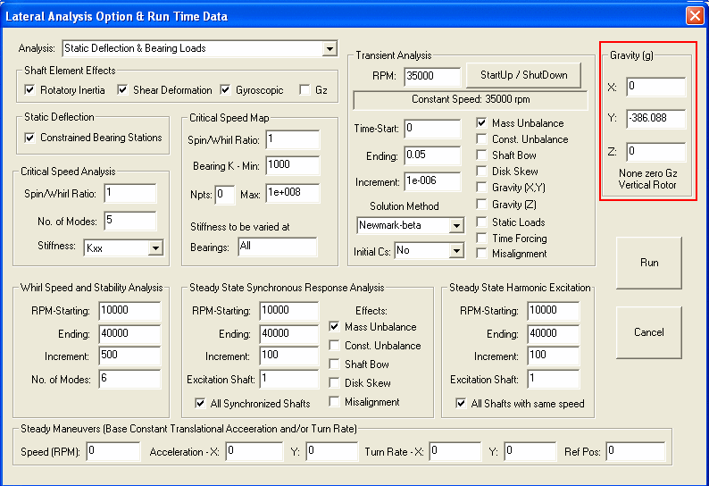
3. Gravity
Gravity constants in X, Y, and Z directions can be specified. Note that Z-axis is the spin axis in DyRoBeS. Since gravity is a vector, the value can be positive or negative. In general, the negative Gy is for the horizontal rotors, and non-zero Gz is for the vertical rotors. For a horizontal rotor, the gravity X and Y affect the forced rotor response and their effects are entered in the right hand side of the equation of motion as forcing vector. For a vertical rotor, the gravity Z affects the rotor free and forced response. Its effect is entered in the stiffness matrix. Typical value of the gravity constant is 386.088 in/s^2 for Unit Systems 1 and 2, and 9.8066 m/s^2 for Unit System 3, and 9806.6 mm/s^2 for Unit System 4.

See also:
Static Deflection and Bearing/Constraint Reactions
Whirl Speed and Stability Analysis
Steady State Synchronous Response Analysis – Linear System
Steady State Synchronous Response Analysis – NonLinear System
Steady State Harmonic Excitation Response Analysis
Time Transient Analysis (Frequency Domain)
Catenary (Gravity Sag) Analysis
Copyright © 2014-2017