Time Transient Analysis (Time Domain)
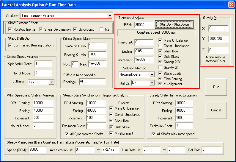
The Time Transient Analysis calculates the transient response for a given constant rotor speed or variable speeds and a specified time interval. The system can be linear or non-linear. The effects of unbalance force (mass and magnet), shaft bow, disk skew, gravity, external static loads, time forcing functions, and misalignment can be turn on or off in the run time data by checking the box. A time interval must be specified for the numerical integration and they are: Start, ending, and incremental time. If you are not sure what time step size (time increment) should be used in the integration, then enter zero in the time increment data field. A default time step size will be provided by the program and then used in the analysis. If you enter the time step size is larger than the recommended value, a message box will prompt you and ask you if you want to change the value. One must exhibit some care with time transient analysis so that the computational times are not excessive. However, for the highly non-linear case, a small time interval is necessary for the solution convergence.
Five solution methods are provided: Gear’s Method, Runge-Kutta, Newmark-beta, Wilson-theta, and Newmark-Modified methods. In general, Wilson-theta provides good convergence. The initial conditions can be specified for the numerical integration, or leave as zeros, or use the previous last point as the initial condition for this run.
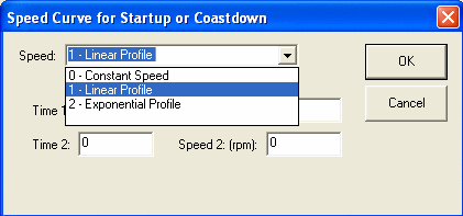
For a constant speed, enter RPM as the rotor speed. For startup and shutdown analysis, click the Startup/Shutdown button for more input. Two speed profiles are available: Linear and Exponential. For more information on the speed curves, click the Speed Curvers here.
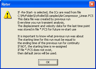
Initial Conditions-YES, a data file containing the initial conditions (displacement and velocity) must be provided.

Initial Conditions-Re-Start
For sample outputs, click Transient Response Plots.
Copyright © 2014-2017