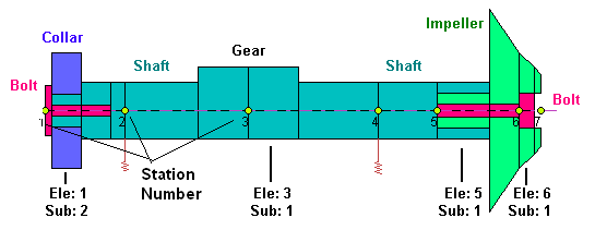
The shafts of the rotor system are numbered consecutively from 1 to Ns and the finite element stations of the model are numbered consecutively starting with 1 at the left end of shaft 1 and continuing to the last station at the right end of shaft Ns. The shafts are made up of Elements with the numbering for each shaft starts at the left end. Stations are located at the ends of the Elements. The term Station is commonly used in the rotordynamics instead of the term Node which is generally used in finite element literature because of the alternate meaning that Node has in the vibration mode shapes. Three types of elements are included in DyRoBeS© and they are: Cylindrical Element, Conical (Tapered) Element, and Userís Supplied Element.
Element i is located immediately to the right of station i. Each element may possess several subelements (starting with 1 at the left of the element) thereby allowing for reasonable flexibility in modeling systems with several geometric discontinuities. Each subelement may possess several levels or layers (starting with zero). The use of subelement is strongly encouraged in the modeling. This will save tremendous computational time with little loss of accuracy in the result. However, when using subelements, it should be kept in mind that Disks and Bearings can only be placed at the ends of the elements (stations).
Note that an element does not exist for the last station of each shaft. For multi-shaft systems, the station numbers are consecutive and the element numbers are not continuous in general. However, in Ver 17. it allows a rigid link between two shafts with the same rotor station and rotor speeds. That means, the starting station of the second shaft has the same station number as the last station of the first shaft. This provides some modeling flexibility for larger rotor system with multiple shafts connected by couplings, such as large turbine-generator sets.

Dual rotor system, two shafts are connected by bearings.
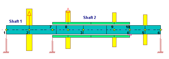
Two-shafts system, two shafts are Rigidly Linked at coupling station.

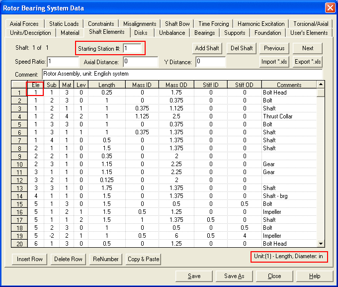
The Shaft Elements input page is shown below:
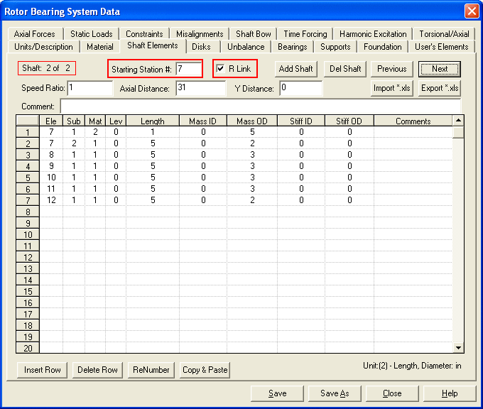
Following shows the second shaft is rigidly linked to the first shaft. This input screen is not related to the previous screen input.
The control buttons <Add Shaft>, <Del Shaft>, <Previous>, and <Next> allow you to add a new shaft data, delete an existing shaft, and switch the shaft data for multi-shaft systems. The <Import *.xls> and <Export *.xls> buttons allow you to import and export the shaft data from and to the MS Excel file. You can manipulate the shaft data in MS Excel and then Import into DyRoBeS. The <Insert Row> and <Delete Row> allow you to insert a new row or delete a row. <ReNumber> allows you to re-number the element and subelement numbers. A new element number is always started with a subelement number 1. <Copy & Paste> allows you to copy and paste row data. Standard Windows commands <Ctrl+C> and <Ctrl+V> can be used to copy and paste a single data field. In the right bottom of the tab, the proper units for the specified unit system are displayed for reference.
The following data fields are explained:
1.Starting Station #: The starting station (also element) number of the current shaft.
Starting Station = 1 for shaft 1. This number is updated automatically and is used to remind the users of the starting element number of that particular shaft. In general, if two shafts are connected by bearings and not rigidly linked together, then the second shaft starting station number (for example 7) is the first shaft last station number (for example 6) plus 1 (6+1=7) in the dual rotor system example shown above. In this dual rotor system, the station number is consecutive (from 6 to 7), but the element number will be not continuous (from 5 to 7). If two rotors are rigidly linked together at coupling with the same rotating speeds as shown in the above figure, then the second shaft starting station number will be the same as the last station number of the first shaft (for example 7 in the above figure). In this case, the station number repeats once (for example 7) and the element number are continuous.
1a.R Link: If the current shaft is Rigidly Linked to the previous shaft, then check this box to avoid the checking features provided in previous version.
2.Speed Ratio: This field is used to calculate the speeds of the multi-shaft systems.
Speed Ratio = 1 for shaft 1. Or you can simply input the shaft rotational speeds,
the program will calculate the ratios for you. Use zero (0) for non-rotating structure.
Positive speed ratio indicates the rotor rotates CCW in the positive Z direction and
negative indicates CW rotation in the negative Z direction for multiple-shafts system.
3.Axial Distance: The distance measured from the station 1 of shaft 1 to the starting
station of the current shaft. It is used for geometric configuration plot only and
it does not affect the numerical results. Distance = 0 for shaft 1.
4.Y Distance: Again, this value is used for geometric plot only. Zeros indicate that the
shafts are concentric, non-zeros are used in the Torsional and Axial multi-branch
systems to represent vertical offset caused by gears, etc..
5.Comment: Comments on the shaft.
6.Ele: Element number. The Element number in the first row must be equal to the
Starting Station #.
7.Sub: Subelement number. Each element can contain a max of 20 subelements. Positive value represents a cylindrical element and negative value indicates that this subelement is a conical (tapered) element.
8.Lev: Level for the subelement. Each subelement can have a max of 10 levels (layers). Level zero (0) is the core data.
9.Mat: Material number for this entry. Mat = 0 for User Supplied Subelement.
10.Length: Subelement length. For the same subelement number with different levels, the subelement length should be the same.
11.Mass ID: Mass inner diameter (For conical element: left end inner diameter).
12.Mass OD: Mass outer diameter (For conical element: left end outer diameter).
13.Stiff ID: Stiffness inner diameter (For conical element: right end inner diameter).
14.Stiff OD: Stiffness outer diameter (For conical element: right end outer diameter).
15.Comments: Description for this entry.
For a standard cylindrical element, the Mass ID and OD are used for kinetic energy (mass, gyroscopic matrices) calculation and the Stiffness ID and OD are used for potential energy (stiffness matrix) calculation. If Stiffness OD = 0, then the Stiffness ID and OD will be reassigned to be equal to the Mass ID and OD. This option can save data entry time if you decide to use the same model for the kinetic energy and potential energy calculation. In the configuration plot, the upper half represents the Mass model and the lower half represents the Stiffness model.
However, for a conical element, the Mass ID and OD are the LEFT end inner and outer diameters and the Stiffness ID and OD are the RIGHT end inner and outer diameters. The mass model and stiffness model are using the same geometry.
Example 1: Single shaft system
A single shaft model and the associated shaft data are shown below:

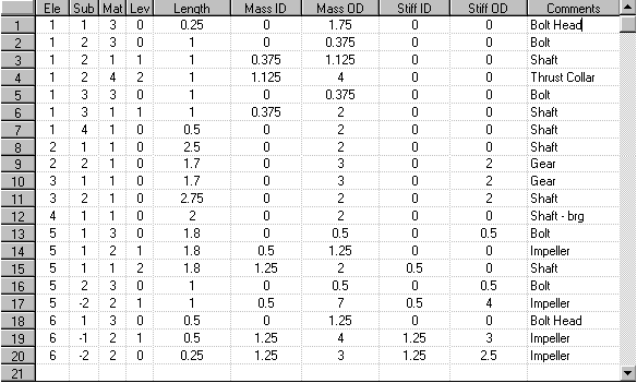
The model shown above has six (6) elements (7 stations). The substations between the major stations are not numbered. The different colors in the shaft elements represent the different material properties. A thrust collar in the left hand side and an impeller in the right hand side are attached to the shaft through bolts. Element 1 Subelement 2, and Element 5 Subelement 1 have three levels. Element 1 Subelement 3, Element 5 Subelement 2, and Element 6 Subelement 1 have two levels. As can be seen from the figure, the bearings are located at the major stations 2 and 4. A bearing cannot be applied at a substation. It is also observed that the rotor (gear portion) is not symmetric about the shaft centerline. The profile above the shaft centerline represents the rotor mass distribution, whereas the distribution below the centerline represents the rotor stiffness distribution.
Example 2: Dual shafts system
A dual shafts model and the associated shaft data are shown below:

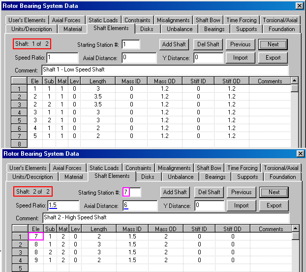
The shaft 1 starts from station 1 to station 6 and shaft 2 is from station 7 to station 10. To add the second shaft data, click the <Add Shaft> button. Note that an element does not exist for the last station of each shaft. The shaft 2 speed is 1.5 times the shaft 1 speed. Note that a positive speed ratio indicates shaft CCW rotation in the positive Z direction and negative indicates shaft CW rotation in the negative Z direction.
Copyright © 2014-2017