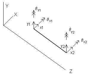
This option allows you to specify your own subelement matrices. An element is assumed to be isotropic, with the (X-Z) and (Y-Z) planes having identical dynamic properties. The rotor shaft centerline is located along the Z-axis. Since the element is isotropic, the stiffness matrix in the X-Z plane is required only. The coordinates for a typical element are shown in the following figure.

The lumped mass system is used for the Useís Element. The element mass and diametral moment of inertia at both end (1-Left and 2-Right) are entered to establish the mass matrix. The mass matrix in the (X-Z) plane will be:
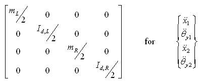
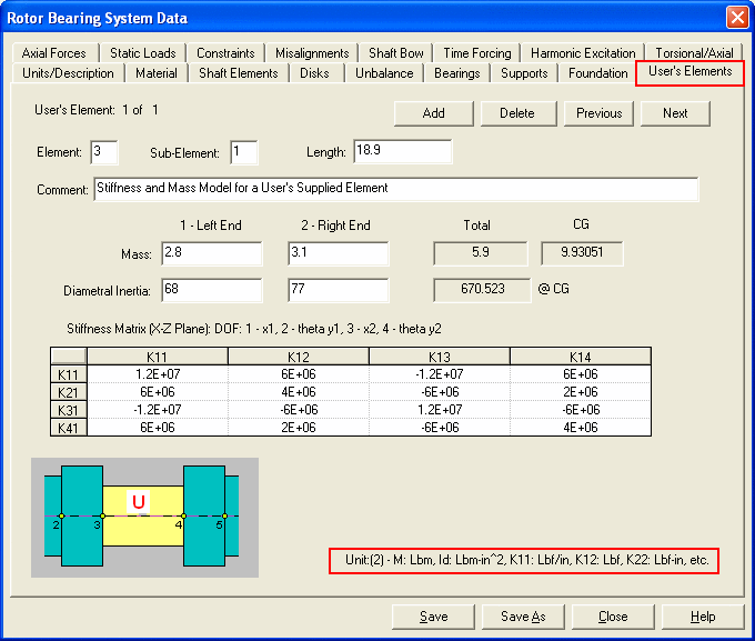
The total element mass, inertia, and CG from the left end are calculated automatically for reference purpose. The element length is needed for the CG and inertia about CG calculation, but, it does not affect the system dynamic results. These mass properties can also be entered in the Rigid/Flexible Disks tab as disks at both ends, and not entered here.
The user supplied (4x4) stiffness matrix in the (X-Z) plane will be:
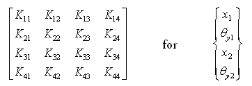
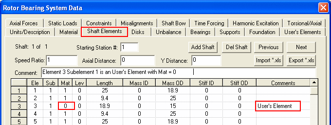
The stiffness matrix is symmetric, therefore only the upper half is used in the formulation of the element stiffness matrix. The Material Number in the Shaft Elements data page should be set to 0 for User Supplied Elements.
See also Shaft Elements,
Copyright © 2014-2017