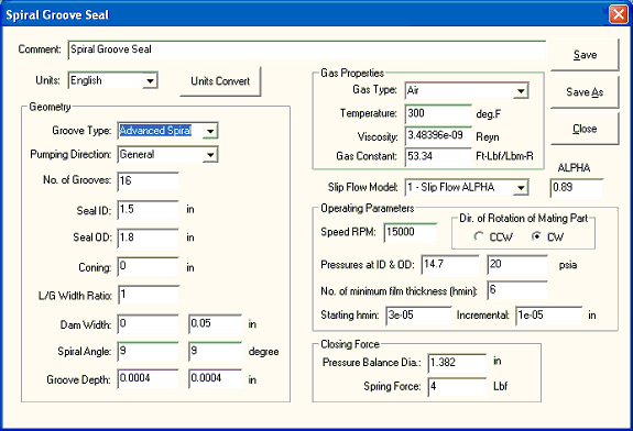
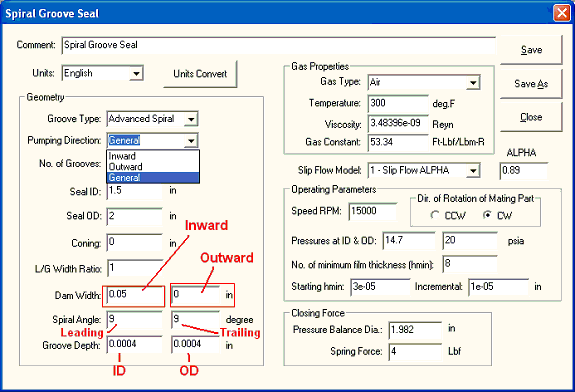
The data input screen is shown below and brief description is given:

Comment: description for the seal under study.
Units: English or Metric units.
Unit Convert: You may convert the units from English to Metrics or from Metrics to English
Geometry
Groove Type: Spiral Groove, Oblique Groove, Radial Groove, and Advanced Groove
For more information see Seal Geometry & Boundary Conditions.
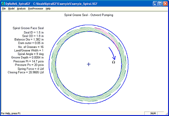
Example for Spiral Groove
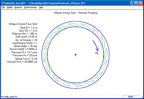
Example for Oblique Groove
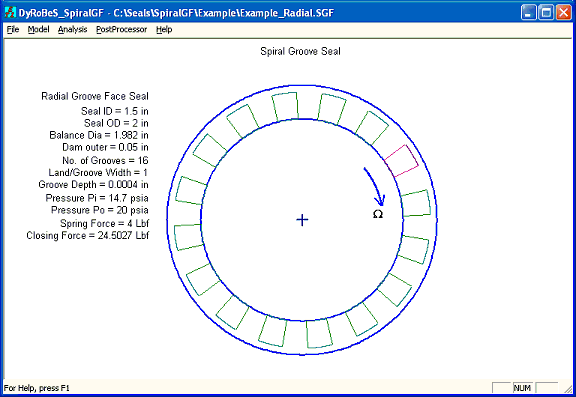
Example for Radial Groove
Advanced Spiral Groove option allows you to build not only the above standard seal geometry, but also many other possibilities.
Pumping Direction: Inward, Outward pumping, or General
A dam exists at the seal ID for inward pumping, and at the seal OD for outward pumping. General options allows for dams at both ID and OD which is NOT common in the face seal applications.
Number of Grooves: Self-explanatory. For more information see Seal Geometry & Boundary Conditions.
Seal ID and OD: Self-explanatory. For more information see Seal Geometry & Boundary Conditions.
Coning: Self-explanatory. For more information see Seal Geometry & Boundary Conditions.
L/G Width Radio: Land / Groove circumferential width ratio. For more information see Seal Geometry & Boundary Conditions.
Spiral Angle: For every spiral groove, there are 2 spiral lines (leading and trailing edges). Commonly there are the same values. In rare cases, they can be different values in advanced spiral groove option. For more information see Seal Geometry & Boundary Conditions.
Groove Depth: Self-explanatory. Typically, the groove depth is a constant value. For advanced groove option, the groove depth can be a linear function from ID to OD. Then the groove depth at ID and OD are entered. For more information see Seal Geometry & Boundary Conditions.
Gas Properties
The Gas Constant, Viscosity, and Temperature are needed for the gas properties. For AIR, once the temperature is specified, the viscosity and gas constant will be auto-updated.
Slip Flow Model
There are 3 options for this selection:
0 No Slip Flow Correction, then Q = 1 in the Reynolds Equation.
1 Slip Flow ALPHA Based on Lin Wus paper.
2 F-K model Based on S. Fukui and R. Kaneko paper.
Operating Parameters
Speed RPM: Self-explanatory.
Direction of Rotation of Mating Part: Self-explanatory. Either CCW or CW.
Pressures at ID and OD: Specify the pressure at boundaries.
No. of Minimum Film Thickness, Starting Hmin, and Incremental Hmin: Minimum film thickness is specified and the opening force is calculated based on this film thickness. The program will calculate the seal performance for a range of minimum film thickness. The minimum film thickness starts from Starting Hmin and incremental Hmin for a total number of No. of Minimum Film Thickness.
Closing Force
One of the user inputs is seal pressure balance diameter, , which can be a bellow mean effective diameter or a secondary seal pressure diameter. The pressure balance diameter effectively divides the pressure on the back of the seal into two zones. The inner zone is exposed to ID pressure Pi and the outer zone is exposed to OD pressure Po. Usually, there is a spring (or magnetic) force that pushes the seal to close. Total closing force = closing force due to pressure + spring force. Let = pressure balance diameter and Fs is the spring force, Total closing force is:

Copyright © 2014-2017