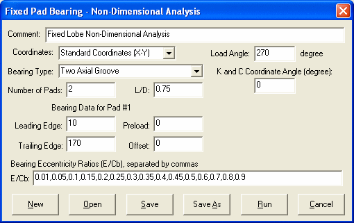
Fixed Lobe Bearing Non-Dimensional Analysis
The non-dimensional bearing analysis is performed based on the given bearing eccentricity ratios (e/Cb). The input eccentricity ratios are separated by a comma in the input string. For a given eccentricity ratio, an iterative procedure in determining the bearing attitude angle is repeated until the convergence criterion is satisfied. The input parameters are:

Bearing Type
Several bearing types are provided in the list for selection. If the bearing under study is not in the list, select the General Fixed Profile type and input the bearing geometrical data. This selection has been made for the convenience of the user since it allows the program to supply the user with typical defaults in Number of Pads, Leading and Trailing Edges, Preload, and Offset. You are free to make your changes on these default data to suit for your need.
Title
Length/Diameter Ratio (L/D)
Bearing Eccentricity Ratios (e/Cb) String
The eccentricity ratio is separated by a comma in the input string.
Number of Pads (Npad)
Two coordinate systems can be used to describe the bearing geometry.
Pad #1 Leading Edge ( 1) and Trailing Edge (
 2)
2)
The Leading Edge and Trailing Edge are the angles in degrees from the reference axis to the leading and trailing edges of the first pad. For the Lund Coordinate System, the reference axis is the negative Load vector (-W). For Standard Coordinate System, the reference axis is the positive X-axis (X).
Preload (m)

Typical Preload value for a fixed lobe bearing ranges from 0.4 to 0.75.
Offset (or Tilt)

where  p, is the angle from the reference axis to the line connecting the bearing center and the pad center of curvature. At this point, the bearing has a minimum clearance for a centered shaft and the lobe arc intersects with bearing base circle. Typical Offset value for a fixed lobe bearing ranges from 0.5 to 1.0.
The coordinate system (x,y,z) used to describe the bearing dynamic coefficients (stiffness and damping coefficients) can be different from the (X,Y,Z) coordinate system used to define the bearing geometry. The Coefficients Coordinate Angle is the angle measured from the X-axis. For Lund Coordinate System, 0 degree (i.e., x-axis is in the loading direction) and 90 degrees (i.e., negative y axis is in the loading direction) are commonly used.
See also Coordinate Systems, Fixed Lobe Bearing Geometry, Fixed Lobe Dimensional Analysis, Nomenclature, Non-Dimensional Parameters, Coefficients Coordinate Angle.
Copyright © 2014-2017