Fixed Lobe Bearing Dimensional Analysis
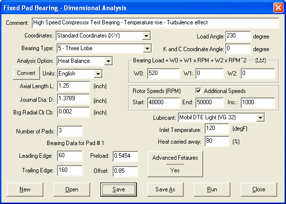
The input screen for the fixed lobe bearing dimensional analysis is shown below and the input parameters are also described below.

Comment
This is used to describe the bearing under study.
Two coordinate systems can be used to describe the bearing geometry. One is the Lund coordinate system where the load vector is collinear with the X-axis. One is the standard coordinate system where X-axis is to the right and Y-axis is to the top. The load vector direction is specified by an angle. Click here to see more description on coordinate systems.

Bearing Type
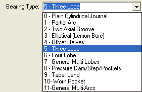
Several bearing types are provided in the list for selection. If the bearing under study is not in the list, select the General Fixed Profile type and input the bearing geometrical data. This selection has been made for the convenience of the user since it allows the program to supply the user with typical defaults in Number of Pads, Leading and Trailing Edges, Preload, and Offset. You are free to make your changes on these default data to suit for your need. Some special bearing types are also included, such as pressure dam bearings, step bearings, multi-pockets bearings, and taper land bearings, etc. These bearings have discontinuity in the bearing clearance and require additional inputs, which are under the Advanced Features button.
Analysis Option
The analysis can be performed in either Constant Viscosity or Heat Balance option. Depending upon the analysis type, the input dialog box changes accordingly. For Constant Viscosity analysis, a non-zero lubricant dynamic viscosity is required, and a lubricant density is needed if turbulence effect is considered. For Heat Balance option, user must select a lubricant from the list, input the oil inlet temperature, and estimate the percentage heat carried away by oil. The operating and maximum film temperatures will be calculated based on heat balance method.


Units
Two systems of units are provided, English or Metric units. See also Units.
Convert Button
The covert button allows you to convert the bearing input data from English to Metric or vice versa between two unit systems.
Axial Length (L)
Bearing (babbitt) axial length.
Journal Diameter (D)
Journal (shaft) diameter.
Bearing Radial Clearance (Cb)
Bearing assembled radial clearance. Cb = (Rb-Rs)
Number of Pads (Npad)
Number of lobes (pads) separated by oil supply grooves. If all the pads (lobes) are identical, only the first pad data are required. If there are not identical, or the Advanced Features are checked, then, each pad (lobe) data must be entered separately.
Pad #1 Leading Edge ( 1) and Trailing Edge (
 2)
2)
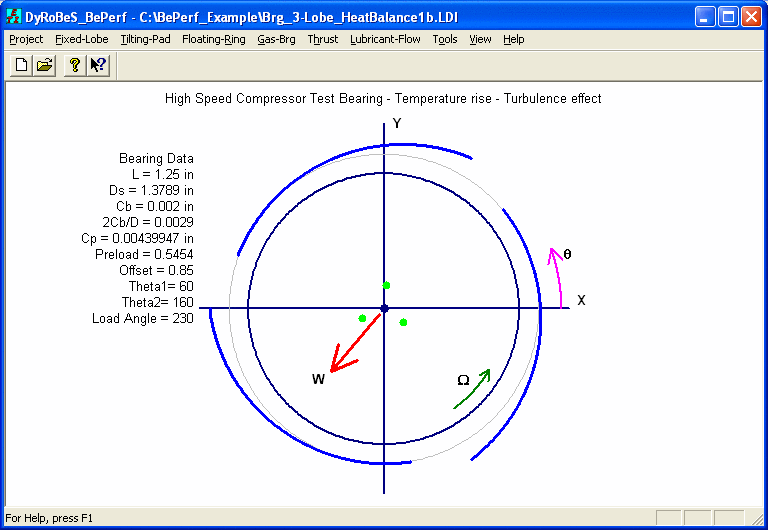
The Leading Edge and Trailing Edge are the angles in degrees from the reference axis to the leading and trailing edges of the first pad. For the Lund Coordinate System, the reference axis is the negative Load vector (-W). For Standard Coordinate System, the reference axis is the positive X-axis (X).
Preload (m)

Typical Preload value for a fixed lobe bearing ranges from 0.4 to 0.75.
Offset

where  p, is the angle from the reference axis to the line connecting the bearing center and the pad center of curvature. At this point, the bearing has a minimum clearance for a centered shaft and the lobe arc intersects with bearing base circle. Typical Offset value for a fixed lobe bearing ranges from 0.5 to 1.0. Offset is meaningful only when preload is not zero.
Load Angle
The load angle is needed (and shown in the input screen) only when the Standard Coordinate system is selected. When Lund coordinate system is selected, the load vector is the same as the X-axis.
The coordinate system (x,y,z) used to describe the bearing dynamic coefficients (stiffness and damping coefficients) can be different from the (X,Y,Z) coordinate system used to define the bearing geometry. The Coefficients Coordinate Angle is the angle measured from the X-axis. For Lund Coordinate System, 0 degree (i.e., x axis is in the loading direction) and 90 degrees (i.e., negative y axis is in the loading direction) are commonly used.
Bearing Load (W)
The bearing load is expressed as a second order polynomial function of rotor speed (rpm). This provides an opportunity to approximate the variation in load with speed.

Rotor Speed (rpm)
Start, End and Increment Speeds specify a list of speeds at which calculations are to be performed.
Additional Speeds
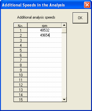
If the Additional Speeds is checked, additional speeds can be entered in additional to the speeds given by the Start, End and Increment Speeds.
Lubricant
This input is for Heat Balance analysis option only. If the lubricant used in the analysis is not in the list, you can enter it from the Edit Lubricant Library under the Lubricant menu.
Inlet Temperature
This input is for Heat Balance analysis option. The lubricant inlet (supply) temperature.
Percent Heat carried Away by Lubricant
This input is for Heat Balance analysis option. Default is 80 %. Typical value for fixed lobe bearings is between 80-90%. The heat generated in the bearing needs to be removed by lubricant and other means. Majority of the heat is removed by lubricant.
Lubricant Dynamic Viscosity
This input is for Constant Viscosity analysis option.
Lubricant Density
This input is for Constant Viscosity analysis option when the Turbulence effect is included. Turbulent effect is included in the Advanced Feature button.
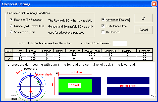
The advanced features allow you to include the turbulence effect, oil flooded, and types of boundary conditions in the circumferential direction. It also allows for the clearance discontinuity in the individual pad. The Advanced Feature must be checked (ON) for bearings with clearance discontinuity, such as Pressure Dam Bearing, Multi-Pocket Bearing, Step Bearing, and Taper Land Bearing. Also, for 3D pressure file plot, the Advanced Feature must be checked. Without Advanced Features, the pads are identical and no discontinuity in the bearing clearance for each pad. Therefore, only one (1) degree-of-freedom at each finite element node, that is, pressure is unknown at each finite element node without the Advanced Feature. However, with Advanced Features, the clearance can have sudden changes, such as pressure dam bearings and taper land bearings, therefore, three (3) degrees-of-freedom at each finite element node are assumed, that is, pressure, and pressure gradients in both axial and circumferential directions at each finite element node are unknown and are to be solved to accommodate the sudden changes in bearing clearance. With Advanced Features ON, the computational time will be greatly increased due to the increase of the degrees-of-freedom.
Although 3 types boundary conditions are provided, one should always use Reynolds boundary condition for design and practical purposes. Sommerfeld and half Sommerfeld (Gumbel) boundary conditions are only provided for educational and research purposes.
Pressure Dam Bearing
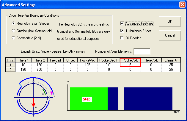
When the PocketAxL = Bearing Axial Length, pressure dam becomes a step as shown below:
Taper Land Journal Bearing, click here for more descriptions on taper land bearings.
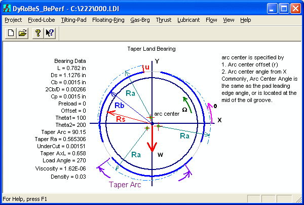
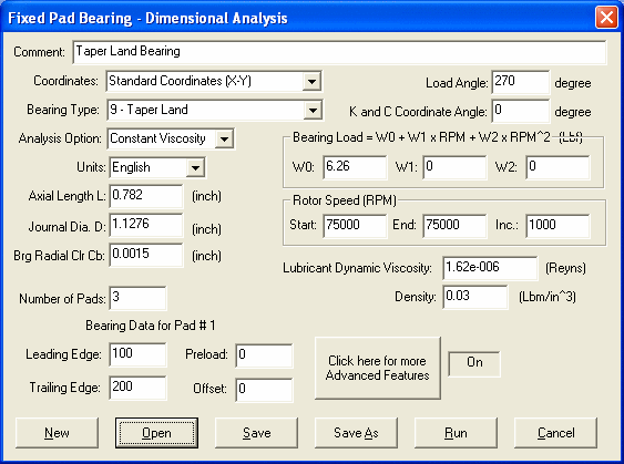
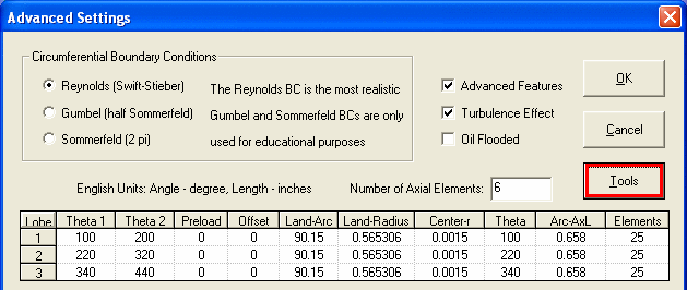
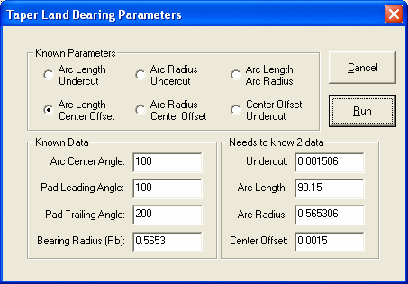
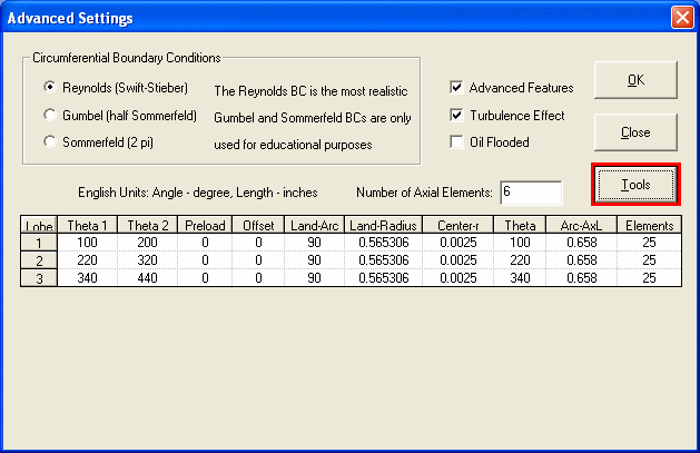
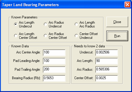
For Taper Land Bearing, the undercut and taper length are normally specified in the design process, however, the arc center and arc radius are typically specified in the manufacturing drawings. A Tools button is provided for this conversion.
See also Coordinate Systems, Fixed Lobe Bearing Geometry, Fixed Lobe Non-Dimensional Analysis, Nomenclature, Examples, Units, Lubricant, Coefficients Coordinate Angle .
Copyright © 2014-2017