Tilting Pad Bearing Dimensional Analysis
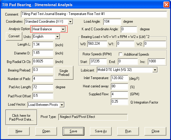
The input parameters for tilting pad bearing dimensional analysis are:

Comment
This is used to describe the bearing under study.
Two coordinate systems can be used to describe the bearing geometry. One is Lund coordinate system where the load vector is collinear with the X-axis. One is standard coordinate system where X-axis is to the right and Y-axis is to the top. The load vector direction is specified by an angle. Click here to see more description on coordinate systems.

Load Angle
The load angle is needed (and shown in the input screen) only when the Standard Coordinate system is selected. When Lund coordinate system is selected, the load vector is the same as the X-axis and it is not displayed on the screen.
Analysis Option
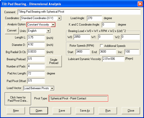
The analysis can be performed in either Constant Viscosity or Heat Balance option. Depending upon the analysis type, the input dialog box changes accordingly. For Heat Balance option, user must select a lubricant from the list, input the oil inlet temperature, and estimate the percentage heat carried away by oil. The operating and maximum film temperatures will be calculated based on heat balance method. In addition, the oil flow rate can be specified for heat balance calculation. If not specified, i.e. zero, then the side leakage will be used for the temperature rise calculation. For Constant Viscosity analysis, a lubricant dynamic viscosity is needed.
Units
Two unit systems are provided, English or Metric units.
See also Units.
Convert Button
The covert button allows you to convert the bearing input data from English to Metric or vice versa between two unit systems.
Length (L)
Bearing (babbitt) axial length.
Diameter (D)
Journal diameter.
Bearing Radial Clearance (Cb)
Bearing assembled radial clearance. Cb = Rb - Rs
Preload (m)

Typical preload value ranges from 0.15 to 0.75 for tilting pad bearings.
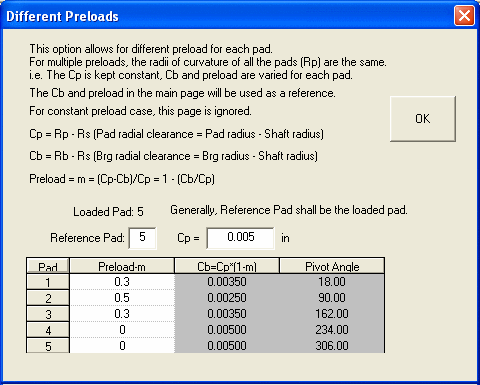
Preload Button
Multiple preloads can be specified, i.e., different preload for different pad. Currently, the pad clearance is fixed, i.e., the pads are identical with the same pad radius. While assembling the bearing, different preloads can be obtained by adjusting the pad location to form different bearing clearance. This restriction will be eliminated in the next release and the user can select which clearance to be fixed.
Number of Pads (Npad)
Number of pads (lobes) supported by pivots.
Pad Arc Length (degrees)

Typical values are 55-60 degrees for 5 pads bearings and 70-75 degrees for 4 pads bearings.
Pad Pivot Offset

where  is the angle from the leading edge of the pad to the pivot point in the direction of shaft rotation. Typical pivot offset value ranges from 0.5 to 0.65.
Load Vector and Pivot Angle ( )
)
The bearing can be orientated such that the load vector is directed onto the pivot, between the pivots, or at any arbitrarily specified pivot angle. Most tilting pad bearings are designed such that the pivots are symmetrical with respect to the load vector, i.e. the load is directed onto a pad pivot or between two pivots. When you select either Load on Pivot or Load between Pivots, then you do not need to input the Pivot Angle (it will not be shown in the screen either). The Pivot Angle will be calculated and updated automatically for you in these two cases.
Pivot angle is the angle in degrees measured from the Negative Load Line for Lundís Coordinate System, and measured from the positive X-axis for Standard Coordinate System to the first pad pivot point measured in the direction of shaft rotation. This angle determines the orientation of the bearing assembly. When you select Specified Pivot Angle in the Load Vector selection, then you need to input the Pivot Angle.

The coordinate system (x,y,z) used to describe the bearing dynamic coefficients (stiffness and damping coefficients) can be different from the (X,Y,Z) coordinate system used to define the bearing geometry. The Coefficients Coordinate Angle is the angle measured from the X-axis to the x-axis. Two most commonly used values for Lund Coordinate Systems are 0 (i.e., x axis is in the loading direction) and 90 degrees (i.e., negative y axis is in the loading direction).
Bearing Load (W)
The bearing load is expressed as a second order polynomial function of rotor speed (rpm). This provides an opportunity to approximate the variation in load with speed.

Rotor Speed (rpm)
Start, End and Increment specify a list of speeds at which calculations are to be performed.
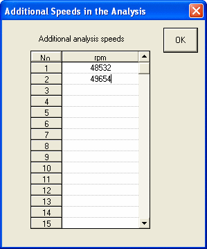
Additional Speeds
If the Additional Speeds is checked, additional speeds can be entered in additional to the speeds given by the Start, End and Increment Speeds.
Lubricant
This input is for Heat Balance analysis option. If the lubricant you want is not in the list, you can enter it from the Edit Lubricant Library under the Lubricant menu.
Inlet Temperature
This input is for Heat Balance analysis option.
Percent Heat carried Away by Lubricant
This input is for Heat Balance analysis option. Typical value is between 75-90%, default is 80%.
Lubricant Supply Flow
This input is for Heat Balance analysis option. If non-zero value is specified, the temperature rise will be calculated based on this flow rate. Otherwise, the side leakage will be used in the temperature rise calculation. In the tilting pad bearing design, end seals are commonly used to reduce the side leakage and the oil flow rate is controlled by either oil supply orifices or drain holes.
For heat balance calculation, the heat generated in the bearing is removed by the effective oil flow. The effective oil flow rate depends on many factors, such as the bearing construction, the specified oil flow rate, side leakage, total circumferential inlet flow, ways to supply the oil, and ways to drain the oil flow, etc. Several cases are considered:
1.When the supplied oil flow rate is NOT specified (i.e., Qsupplied = 0), the side leakage will be used as the effective oil flow. This is the default option and is commonly required in the bearing design process to determine the minimum required flow rate.
Qsupplied = 0, => Qeffective = Qside
2. When the specified oil flow rate is less than and equal to the side leakage (i.e., Qsupplied <= Qside ), the specified flow rate will be used as the effective flow rate. Note, this starvation will result in overheated bearing and is not desirable.
Qsupplied <= Qside, => Qeffective = Qsupplied
Q Integration Factor
Typical value for this Q integration factor from many test data shows that the value is between 0.2 and 0.4 with an average of 0.25 to 0.3.
Lubricant Dynamic Viscosity
This input is for Constant Viscosity analysis option.
Pad/Pivot Data
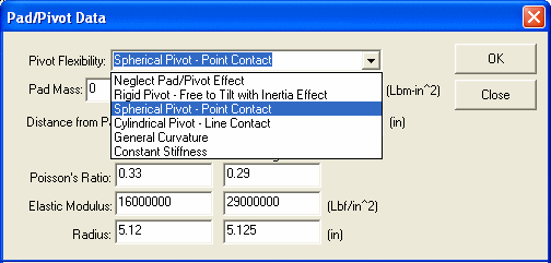
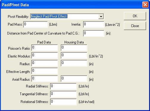
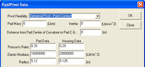
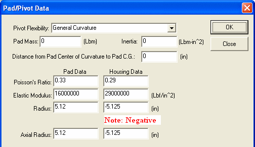
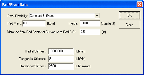
Several types of Pad/Pivot configurations are available in this program. When you click on Pad/Pivot Data Button, a new dialog box will pop-up as shown below. The input parameters are based on the type of Pivot Flexibility selection. The dialog box will change itself depending upon the selection. Only the parameters required will appear in the dialog box. For Spherical Pivot and Cylindrical Pivot, the radii are always positive. For General Curvatures, the radii are positive if the center of curvature lies within the given body, i.e., the surface is convex, otherwise, the radii are negative. The pivot stiffness is derived from the deflection equation (references, Young and Hamrock). Caution must be taken when input Rotational Stiffness for Flexure Pad Bearing. The pad assembly method for tilting pad bearing is based on the assumption that the pads are free to tilt about the pivot points.

See also Coordinate Systems, Tilting Pad Bearing Geometry, Tilting Pad Non-Dimensional Analysis, Fixed Lobe Bearing Geometry, Nomenclature, Units, Lubricant, Examples, Coefficients Coordinate Angle .
Copyright © 2014-2017