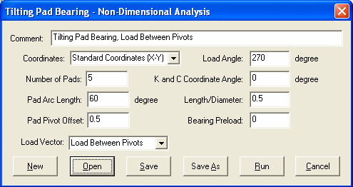
Tilting Pad Bearing Non-Dimensional Analysis
In the non-dimensional tilting pad bearing analysis, the effects of pad inertia and pivot flexibility are neglected.
Number of Pads (Npad)
Two coordinate systems can be used to describe the bearing geometry.
Pad Arc Length (degrees)

Typical values are 57 degrees for 5 pads bearings and 72 degrees for 4 pads bearings.
Pad Pivot Offset

where  is the angle from the leading edge of the pad to the pivot point in the direction of shaft rotation. Typical pivot offset value ranges from 0.5 to 0.65.
Length/Diameter Ratio (L/D)
Bearing length / diameter ratio.
Preload (m)

Typical preload value ranges from 0.15 to 0.75 for tilting pad bearings. Multiple preloads are allowed with a constant Cp. The different preloads are separated by a comma in the input string. That is, one can enter a preload string, such as, 0.5,0.5,0.3,0.3 for a 4-pads bearing and 0.4,0.5,0.4,0.25,0.25 for a 5-pads bearing. If only one preload value is entered, then it is a constant preload bearing. For multiple preloads, the various Cb for each pad are calculated based on the pad preload value and the constant Cp.

In the data normalization, preload at the loaded pad will be used. That is the Cb at the loaded pad will be used as the reference.
Load Vector and Pivot Angle ( )
)
The bearing can be orientated such that the load vector is directed onto the pivot, between the pivots, or at any arbitrarily specified pivot angle. Most tilting pad bearings are designed such that the pivots are symmetrical with respect to the load vector, i.e. the load is directed onto a pad pivot or between two pivots. When you select either Load on Pivot or Load between Pivots, then you do not need to input the Pivot Angle. The Pivot Angle will be calculated and updated automatically for you in these two cases.
Pivot angle is the angle in degrees measured from the Negative Load Line for Lundís Coordinate System and measured from the positive X-axis for Standard Coordinate System to the first pad pivot point measured in the direction of shaft rotation. This angle determines the orientation of the bearing assembly. When you select Specified Pivot Angle in the Load Vector selection, then you need to input the Pivot Angle.
The coordinate system (x,y,z) used to describe the bearing dynamic coefficients (stiffness and damping coefficients) can be different from the (X,Y,Z) coordinate system used to define the bearing geometry. The Coefficients Coordinate Angle is the angle measured from the X-axis to the x-axis. Two most commonly used values for Lund Coordinate Systems are 0 (i.e., x axis is in the loading direction) and 90 degrees (i.e., negative y axis is in the loading direction).
Comments
See also Coordinate Systems, Tilting Pad Bearing Geometry, Tilting Pad Dimensional Analysis, Nomenclature, Examples, Fixed Lobe Bearing Geometry, Non-Dimensional Parameters, Coefficients Coordinate Angle .

Copyright © 2014-2017